Eureka AIR delivers breakthrough ideas for toughest innovation challenges, trusted by R&D personnel around the world.

Lens for LED lamp

A technology for LED lamps and lenses, which is applied in the parts of lighting devices, semiconductor devices of light-emitting elements, lighting devices, etc., can solve the problems of uneven light distribution of LED chips and the like

Inactive Publication Date: 2011-05-25
HENGDIAN GRP TOSPO LIGHTING
View PDF3 Cites 0 Cited by
  • Summary
  • Abstract
  • Description
  • Claims
  • Application Information

AI Technical Summary

Problems solved by technology

However, the light distribution of the LED chip is uneven, and it emits light from one side, that is, the maximum light-emitting angle of the LED chip is 180 degrees, which will be a stumbling block for it to replace the incandescent lamp

Method used


Image

  • Lens for LED lamp
  • Lens for LED lamp
  • Lens for LED lamp

Examples


Embodiment 1

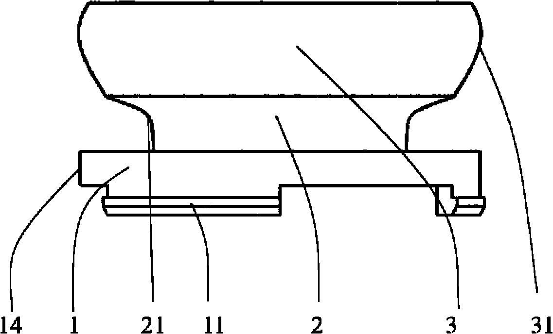
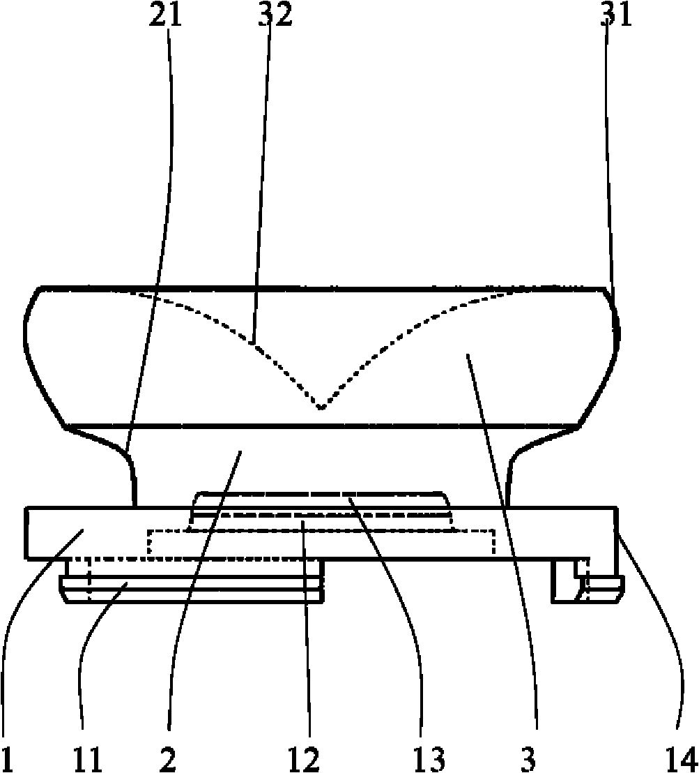
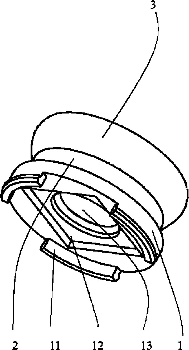
[0023] reference Figure 1 to Figure 3 As shown, a preferred implementation structure for an LED lens provided by the present invention includes a fixed base 1, a first beam splitter 2 and a second beam splitter 3.

[0024] The fixed base 1 is located at the bottom end of the lens. The fixed base 1 includes a cylinder 14 and three buckles 11. The number of buckles can be set according to specific requirements. The structure of the buckles can also be varied. Too much repeat. At the bottom of the fixed base 1, there is a space 12 for placing the LED chip. This space 12 is also determined according to the shape of the specific LED chip. The upper space 13 of the chip is used to initially distribute the light emitted by the LED chip. This space 13 is similar Round truncated space, the height of the space depends on the specific LED chip.

[0025] The first luminous body 2 is located on the fixed base 1, and the diameter of the upper surface of the fixed base 1 is larger than the diam...

Embodiment 2

[0029] Please refer again Figure 4 to Figure 6 Shown is another preferred implementation structure improved by this invention, which also consists of a fixed base 1, a first beam splitter 2 and a second beam splitter 3. The biggest difference from the foregoing structure is that the diameter of the upper surface of the first beam splitter 2 is larger than the diameter of the lower surface of the second beam splitter 3, and the second beam splitter 3 is a truncated cone-shaped structure with a larger lower surface diameter and a smaller upper surface diameter. The first beam splitter 2 of this implementation structure does not reflect the light that is transmitted to the side surface 21 of the first beam splitter from the light after the initial distribution to the second beam splitter 3, but directly passes through the side surface 21 of the first beam splitter. The light is reflected into the air; furthermore, the light directly transmitted to the upper surface 22 of the firs...


PUM


Abstract

The invention provides a lens for a light emitting diode (LED) lamp. The lens enables an LED to realize light emission in a total space, and avoids the defect of single-side light emission of an LED chip; and the lens applied in the LED bulb lamp can realize the same light emitting effect as an incandescent lamp. The lens for the LED lamp comprises a lens fixed pedestal, a first luminous body and a second luminous body, which are symmetrical around the same central axis; the first luminous body is positioned on the fixed pedestal; the second luminous body is positioned on the first luminous body; the first luminous body has a round table structure, the bottom diameter of which is short and the upper diameter of which is long; and the side of the longitudinal section of the round table structure is an inwards sunken smooth curve.

Description

Technical field [0001] The invention relates to a lens, in particular to a lens of an LED lamp. Background technique [0002] In the era of rapid technological development, low-carbon and energy-saving is an unstoppable trend. LEDs have the advantages of low power consumption, long life, and high luminous efficiency. There is no doubt that the development trend of the LED lighting industry has attracted everyone's attention. At present, LED lighting technology is also improving day by day, and the advantages of LED applications in the lighting industry will be more obvious. The replacement of energy-saving lamps with LED lighting in the next few years has been the consensus of the industry. However, the light distribution of the LED chip is uneven, and it emits light from one side, that is, the maximum light-emitting angle of the LED chip is 180 degrees, which will be a stumbling block to replace the incandescent lamp. The light of the incandescent lamp covers the entire space, ...

Claims


Application Information

Patent Timeline
IPC IPC(8): F21V5/04F21Y101/02F21Y115/10
Inventor 孙清波贾成真
Owner HENGDIAN GRP TOSPO LIGHTING
Why Eureka
Eureka Blog
Learn More