Linearly polarized light-based polarization tracking system and method

A linearly polarized light and tracking system technology, applied in the direction of using optical devices, using feedback control, measuring devices, etc., can solve the problem of low tracking accuracy, and achieve the effects of guaranteed accuracy, precise polarization tracking, and high precision

Active Publication Date: 2011-05-25
HARBIN INST OF TECH
View PDF6 Cites 27 Cited by
  • Summary
  • Abstract
  • Description
  • Claims
  • Application Information

AI Technical Summary

Problems solved by technology

[0003] In order to solve the problem of low tracking accuracy of the existing polarization tracking method, the present invention provides a polarization tracking system and method based on linearly polarized light

Method used


Image

  • Linearly polarized light-based polarization tracking system and method
  • Linearly polarized light-based polarization tracking system and method
  • Linearly polarized light-based polarization tracking system and method

Examples


specific Embodiment approach 1

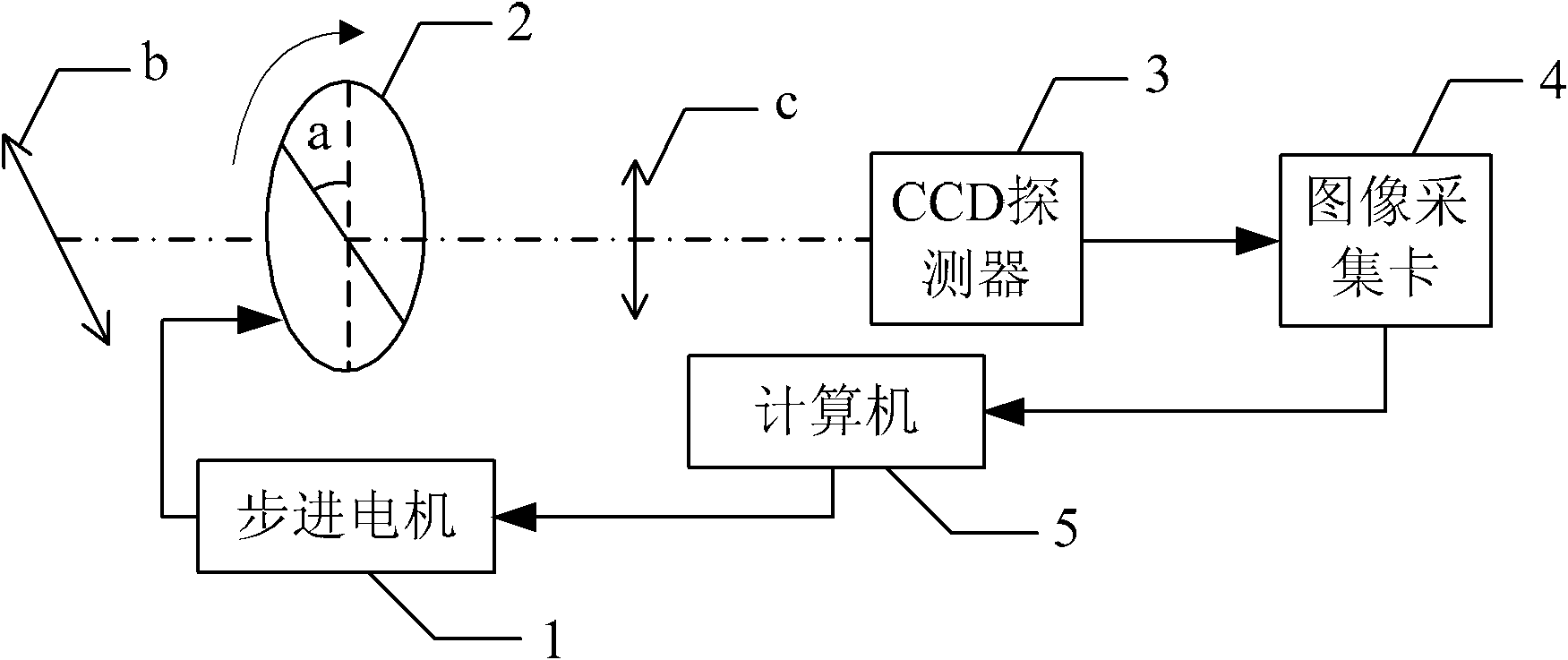
[0011] Specific implementation mode 1. Combination figure 1 Illustrate this specific embodiment, a kind of polarization tracking system based on linearly polarized light, it comprises computer 5, and it comprises stepper motor 1, analyzer 2, CCD detector 3 and image acquisition card 4, analyzer 2 is fixed on On the output shaft of the stepper motor 1, the incident linearly polarized light is incident on the detection surface of the CCD detector 3 through the analyzer 2, and the image signal output end of the CCD detector 3 is connected to the image signal input end of the image acquisition card 4 connected, the image grayscale signal output end of the image acquisition card 4 is connected with the image grayscale signal input end of the computer 4, the control signal output end of the computer 4 is connected with the control signal input end of the stepping motor 1, and the The analyzer 2 can be rotated 360 degrees along the optical axis of the incident light.

specific Embodiment approach 2

[0012] Embodiment 2. The difference between this embodiment and the linearly polarized light-based polarization tracking system described in Embodiment 1 is that the model of the CCD detector 3 is MTV-1801.

[0013] This embodiment selects the CCD camera of MTV-1801 produced by Taiwan Mintong Company, and its main parameters are as follows: number of pixels 795 (H) × 596 (V); spectral response range 400nm~1100nm; resolution 600TVL; detection sensitivity 0.021lx; The signal-to-noise ratio is greater than 46dB; the working temperature is -10℃~50℃.

specific Embodiment approach 3

[0014] Embodiment 3. The difference between this embodiment and the polarization tracking system based on linearly polarized light described in Embodiment 1 is that the image acquisition card 4 is a video data acquisition card based on the 1394 protocol.


PUM


Abstract

The invention discloses a linearly polarized light-based polarization real-time tracking method, which relate to a polarization tracking system and a polarization tracking method. The invention solves the poor real-time tracking problem of the conventional polarization tracking method. In the system, a polarization analyzer is fixed on an output shaft of a step motor, a detection face of a charge coupled device (CCD) detector acquires incident light transmitted in the polarization analyzer and outputs an image to the computer through an image acquisition card, and the control signal output end of the computer is connected with the control signal input end of the step motor. In the method, the detection face of the CCD detector detects the incident light and generates an image, the image acquisition card detects the gray scale of the image, the computer calculates according to a detected value to obtain the polarization direction change information of the incident light and drive the step motor to drive the polarization analyzer to rotate to a direction consistent with the polarization direction of incident light, and thus, the polarization tracking of the incident light is realized. The system and the method are applicable to the polarization tracking of linearly polarized light.

Description

technical field [0001] The invention relates to a polarization tracking system and method. Background technique [0002] For the coherent space laser communication system, it is necessary to use linearly polarized light as the beacon light and signal light. The high-precision tracking of the polarization direction of the incident laser beam is a major prerequisite to ensure its normal operation. However, the space environment where the coherent space laser communication system is located is relatively complex, and there is currently no good method to solve the problem of precise tracking of the laser polarization direction. Contents of the invention [0003] In order to solve the problem of low tracking accuracy of the existing polarization tracking method, the present invention provides a polarization tracking system and method based on linearly polarized light. [0004] A polarization tracking system based on linearly polarized light, which includes a computer, which i...

Claims


Application Information

Patent Timeline
Patent Type & Authority Applications(China)
IPC IPC(8): G05D3/12G01B11/26
Inventor 王强马晶谭立英于思源韩琦琦付森宋义伟
Owner HARBIN INST OF TECH
Why Eureka
Try Eureka