Radioactive source supervision system and method

A monitoring system and radioactive source technology, applied in the field of monitoring systems for radioactive sources, can solve the problems of no anti-dismantling function, single monitoring technical means, low degree of informatization, etc., to reduce the difficulty of installation, good system integrity, Clear system architecture

Inactive Publication Date: 2011-05-25
FOCUSED PHOTONICS +2
View PDF8 Cites 14 Cited by
  • Summary
  • Abstract
  • Description
  • Claims
  • Application Information

AI Technical Summary

Problems solved by technology

[0004] 1. The monitoring technology is single and cannot meet the requirements of various applications
[0005] 2. The main purpose of the traditional radiation dose meter is to measure the environmental radiation dose in the place, which is too large to be installed near the radioactive source.
[0006] 3. GPS positioning has great limitations, it is not practical in indoor occasions, and it has no anti-demolition function
[0007] 4. Simple technical means: simple dose and positioning monitoring, lack of new technology applications, no scientific and reasonable solutions for multiple sources in one enterprise, no effective and reliable monitoring means for radioactive sources moving in a small area within the enterprise and entering and leaving the factory area, lack of The technical realization of integrating enterprise behavior into the environmental protection scientific management system
[0008] 5. Simple management model: low degree of informatization, simple system structure, lack of regional macro management concepts and innovation models, simple monitoring of objects, and failure to incorporate corporate behavior into an effective regulatory system

Method used


Image

  • Radioactive source supervision system and method
  • Radioactive source supervision system and method
  • Radioactive source supervision system and method

Examples


Embodiment 1

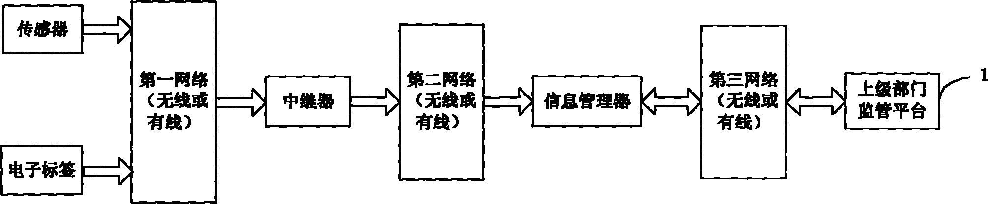
[0087] figure 1 A basic structural diagram of the radioactive source monitoring system in Embodiment 1 of the present invention is schematically given. Such as figure 1 As shown, the radioactive source supervision system includes:

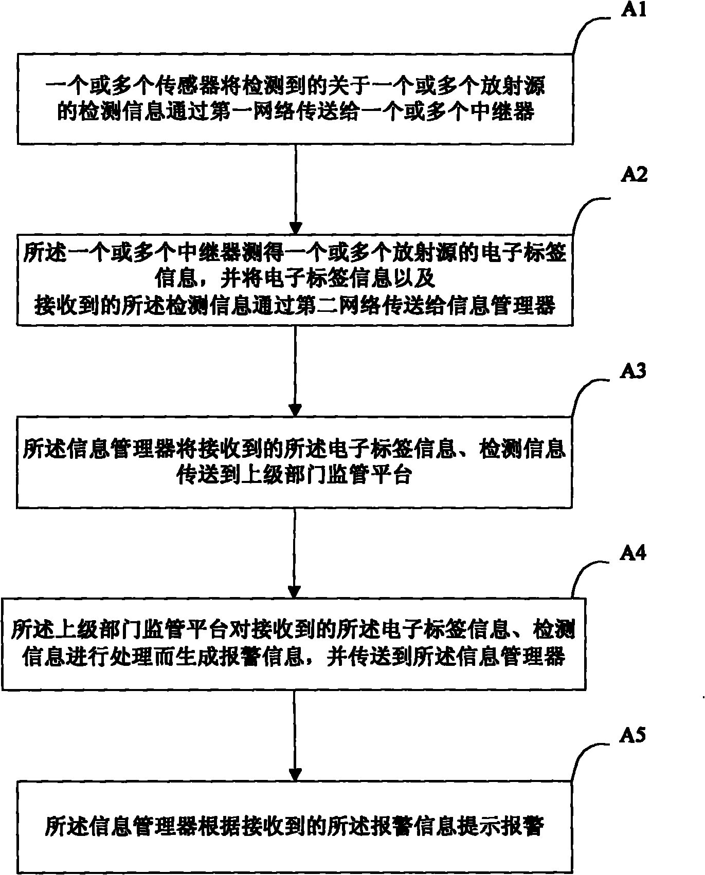
[0088] one or more sensors for transmitting detected detection information about one or more radioactive sources to one or more repeaters via a first network (wired or wireless); The detection information includes the radiation dose of the one or more radiation sources; the one or more sensors have an anti-tampering function.

[0089] one or more electronic tags, the one or more electronic tags are arranged on the container of the one or more radioactive sources for identifying the location of the one or more radioactive sources;

[0090] One or more repeaters, the one or more repeaters are used to measure the information of the one or more electronic tags, such as using radio frequency technology, and the electronic tag information, the receive...

Embodiment 2

[0117] Figure 4A basic structural diagram of the radioactive source monitoring system in Embodiment 2 of the present invention is schematically given. Such as Figure 4 As shown, the difference between the radioactive source supervision system and embodiment 1 is that it further includes:

[0118] One or more inspection personnel equipment, the one or more inspection personnel equipment is used to transmit the feature code generated by the one or more sensors to the supervisory platform of the superior department through the fourth network (wired or wireless); The above-mentioned feature code is a dynamic feature code sent out periodically, which is used to uniquely identify different radioactive sources. The one or more inspector devices can transmit the feature code to the supervisory platform of the superior department through a communication device such as a mobile phone or a computer, using communication technologies such as CDMA and GSM.

[0119] The one or more sens...

Embodiment 3

[0134] Figure 7 A basic structural diagram of the radioactive source monitoring system in Embodiment 3 of the present invention is schematically given. Such as Figure 7 As shown, the difference between the radioactive source monitoring system and embodiment 2 is that it further includes:

[0135] requesting means for requesting movement of the one or more radiation sources based on user input using the one or more radiation sources.

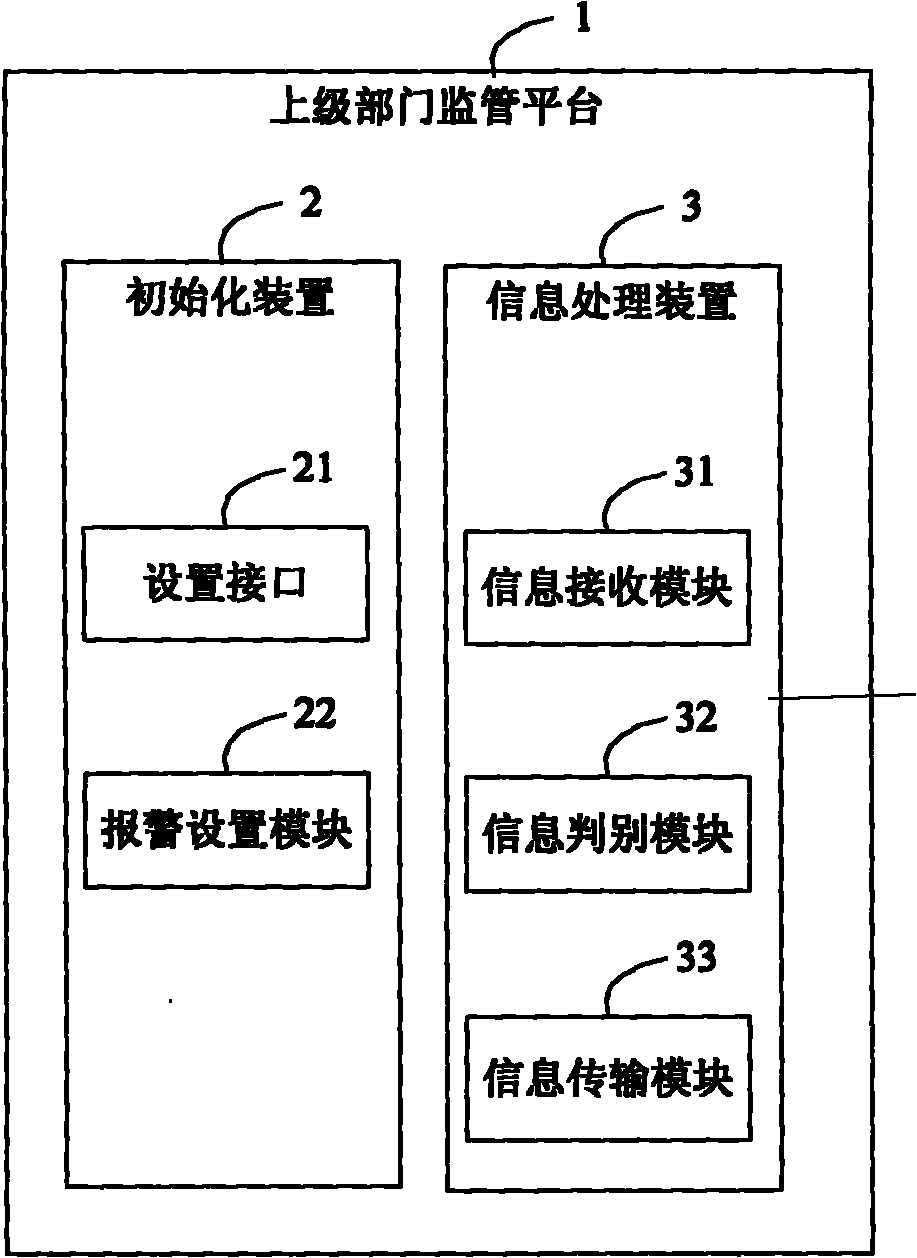
[0136] Figure 8 A schematic frame diagram of the basic components of the upper-level department supervision platform in Embodiment 3 of the present invention is given. Such as Figure 8 As shown, the difference between the upper-level department supervision platform and embodiment 2 is that the upper-level department supervision platform includes:

[0137] An application processing device 4, the application processing device 4 is configured to receive and process the application for moving the one or more radioactive sources transmitted t...


PUM


Abstract

The invention provides a radioactive source supervision system. The radioactive source supervision system comprises a sensor, an electronic tag, a repeater, an information manager and a superior department supervision platform, wherein the sensor is used for transmitting the detected detection information about a radioactive source to the repeater; the detection information comprises radiation dose of the radioactive source; the electronic tag is used for marking the position of the radioactive source; the repeater is used for measuring the information of the electronic tag and transmitting the information of the electronic tag and the received detection information to the information manager; the information manager is used for transmitting the received information of the electronic tag and the received detection information to the superior department supervision platform and prompting alarm according to the alarm information; and the superior department supervision platform is used for processing the received information of the electronic tag and the received detection information to generate the alarm information and transmitting the alarm information to the information manager. The system has the advantages of comprehensive function, low cost and the like, and is convenient to implement.

Description

technical field [0001] The invention relates to a monitoring system and method, in particular to a monitoring system and method for radioactive sources. Background technique [0002] The traditional monitoring of radioactive sources only monitors the radioactive intensity of radioactive sources, that is, dose rate monitoring. The method is to install detectors at a certain distance from the radioactive sources and transmit them to the central controller through data lines. Some more complex systems will add video surveillance, radioactive source coordinate monitoring (GPS), etc. At the same time, the data is transmitted to the monitoring center by the combination of IE network data transmission, wireless microwave data transmission and GPRS data transmission. [0003] The above radioactive source monitoring system has many deficiencies: [0004] 1. The single monitoring technology means cannot meet the requirements of various application occasions. [0005] 2. The main pu...

Claims


Application Information

Patent Timeline
Patent Type & Authority Applications(China)
IPC IPC(8): G08B21/12G06K7/00G01T1/02
Inventor 郭锴万学平王侃李岭
Owner FOCUSED PHOTONICS
Why Eureka
Try Eureka