
Joint connector, wiring harness and method for assembling the joint connector

A joint connector, connector technology, applied in the direction of the parts of the connecting device, the connecting contact material, the two-part connecting device, etc.

Active Publication Date: 2011-05-25
SUMITOMO WIRING SYST LTD
View PDF6 Cites 7 Cited by
  • Summary
  • Abstract
  • Description
  • Claims
  • Application Information

AI Technical Summary

Problems solved by technology

In this case, for example, the vertically extending leg portion of the stand will be extended

Method used


Image

  • Joint connector, wiring harness and method for assembling the joint connector
  • Joint connector, wiring harness and method for assembling the joint connector
  • Joint connector, wiring harness and method for assembling the joint connector

Examples


Embodiment Construction

[0077] refer to Figure 1 to Figure 18 An embodiment of the present invention will be described.

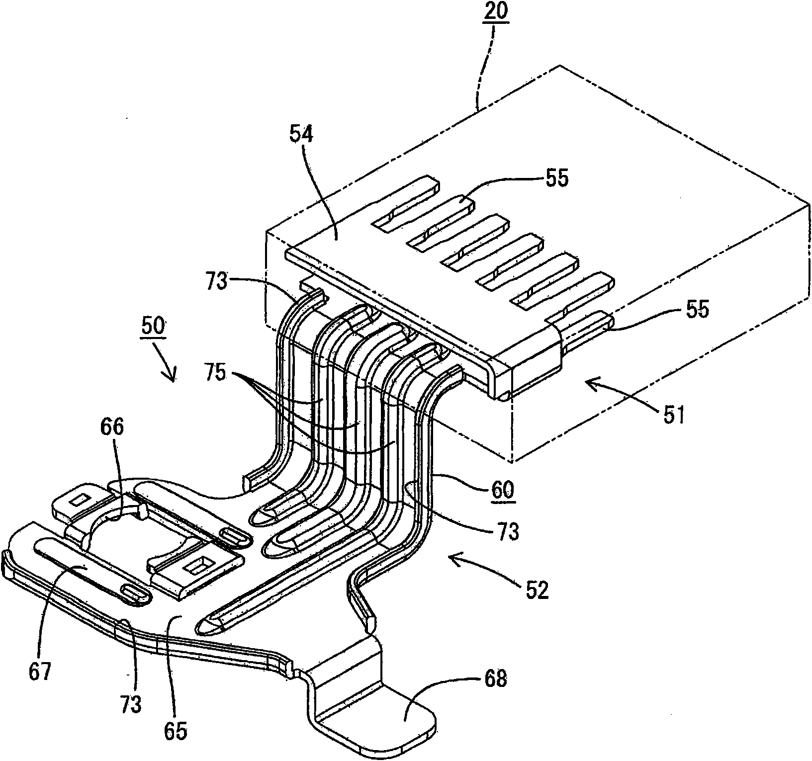
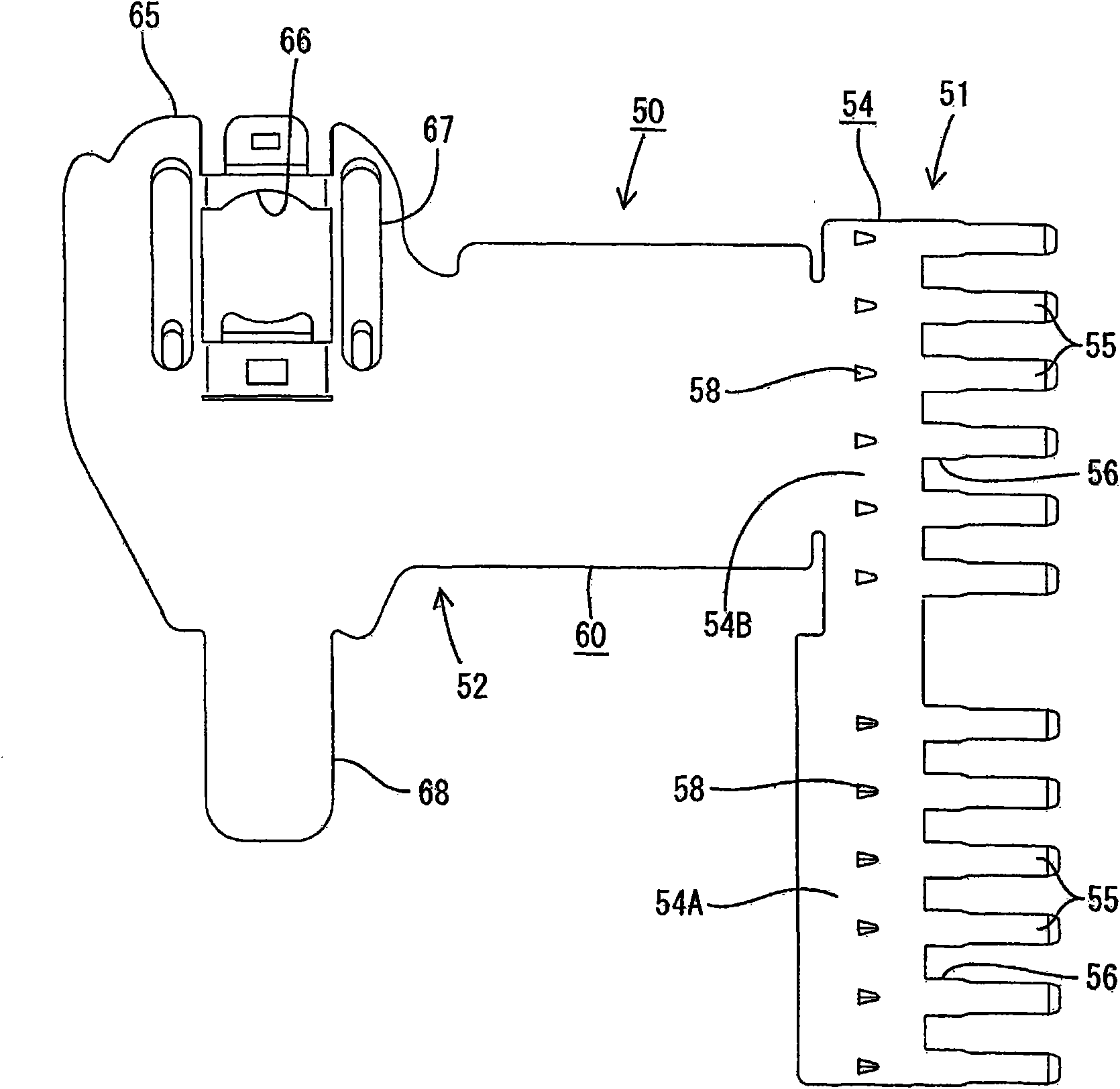
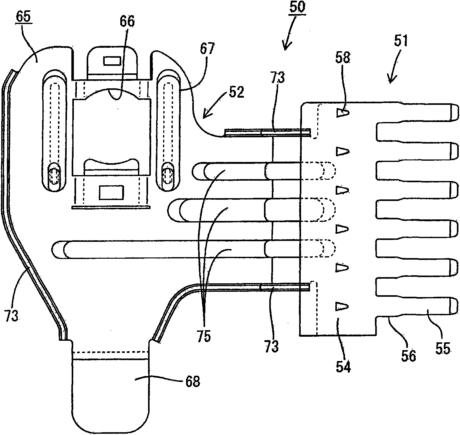
[0078] The joint connector JC of this embodiment is configured such that the male terminal portion 51 of the joint terminal 50 is installed in the front side of the connector housing 20, and is connected to one or more female terminals on one or more ends of each ground wire 10. 11 is installed into the connector housing 20 (preferably substantially from the rear) so as to be connected to one or more corresponding male terminals 55 provided in the male terminal portion 51, as figure 1 with Figure 9 As shown in , and the bracket 52 of the connector terminal 50 is to be mounted on the ground of the vehicle.

[0079] The connector housing 20 (hereinafter simply referred to as "housing 20") is made of synthetic resin, for example, and / or is substantially as Image 6 with Figure 7 The platform form shown in . Roughly speaking, the front side ( Figure 7 The left side in ) is u...


PUM


Abstract

The invention relates to a joint connector, a wiring harness and a method for assembling the joint connector. An object of the invention is to increase a bending strength of a joint part between a male terminal portion and a bracket in a joint terminal. A ground joint connector has a housing and a plurality of side by side cavities arranged in the housing for receiving female terminals. The ground joint connector also has a joint terminal including a male terminal portion with male terminals to be accommodated in the respective cavities, and a bracket connected with the male terminal portion and including a mounting portion to be mounted on a grounding portion. The bracket extends in an extending direction of the cavities from the rear edge of the male terminal portion and then is bent twice to define a crank shape. The mounting portion is formed by a flat portion on the front end of the bracket. Reinforcing flanges and ribs are formed on a flat portion at a base end side of the bracket. The housing includes receiving portionsfor tightly holding back ends of the flanges and the ribs.

Description

technical field [0001] The present invention relates to a ground joint connector, a wire harness using the joint connector, and a method of assembling the joint connector. Background technique [0002] A joint connector for connecting a plurality of ground wires to a vehicle ground at one time is generally known from Japanese Unexamined Patent Publication No. 2000-77140. It is provided with a connector housing formed by a plurality of cavities arranged side by side and into which a female terminal connected to an end of a ground wire can be inserted body; and joint terminals to be installed in the connector housing. The joint terminal has a structure such that a bracket bent into an L shape is connected to a rear edge of a male terminal part including a plurality of male terminals to be accommodated in each cavity and having base ends connected to each other, and forming A mounting portion having a mounting hole is formed at the flat portion at the front end side of the br...

Claims


Application Information

Patent Timeline
Patent Type & Authority Applications(China)
IPC IPC(8): H01R13/02H01R13/20H01R13/46H01R13/652H01R24/28H01R43/20
CPCH01R11/12H01R31/085H01R13/631H01R4/64H01R13/4362
Inventor 原照雄今井裕次郎
Owner SUMITOMO WIRING SYST LTD
Features
  • Generate Ideas
  • Intellectual Property
  • Life Sciences
  • Materials
  • Tech Scout
  • Unparalleled Data Quality
  • Higher Quality Content
  • 60% Fewer Hallucinations
Learn More