Error detection device and control method for laser communication link beams

A laser communication and detection device technology, applied in measuring devices, optical devices, transmission monitoring/testing/fault measurement systems, etc., can solve poor control stability, high-frequency vibration of satellite platforms cannot be effectively compensated, rough aiming and fine aiming The control is prone to problems such as mutual coupling, so as to avoid mutual coupling problems, realize system miniaturization, stable high-precision control, and high-frequency stable beam control.

Inactive Publication Date: 2011-05-25
HARBIN INST OF TECH
View PDF3 Cites 18 Cited by
  • Summary
  • Abstract
  • Description
  • Claims
  • Application Information

AI Technical Summary

Problems solved by technology

[0005] The purpose of the present invention is to solve the problem of using a single CCD for error detection and controlling the light beam to reduce the overall working bandwidth of the system, which cannot effectively compensate the high-frequency vibration of the satellite platform; problem, providing an error detection device and control method for a laser communication link beam

Method used


Image

  • Error detection device and control method for laser communication link beams
  • Error detection device and control method for laser communication link beams
  • Error detection device and control method for laser communication link beams

Examples


specific Embodiment approach 1

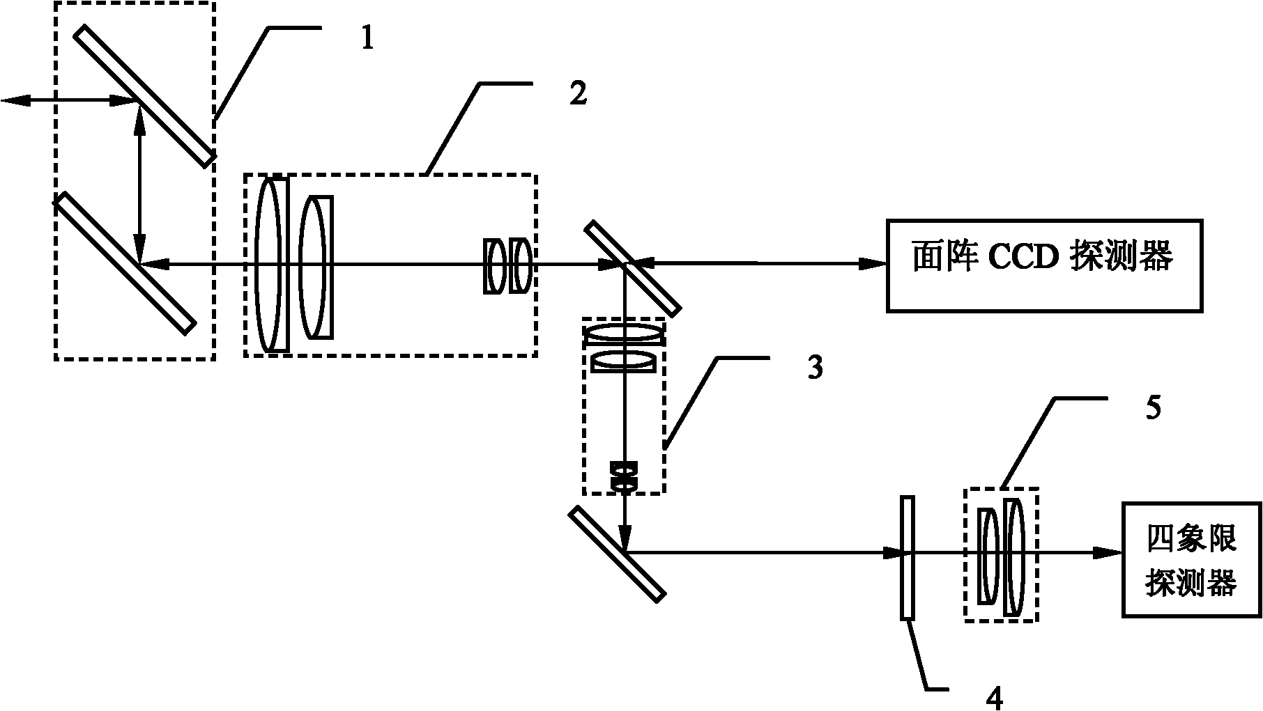
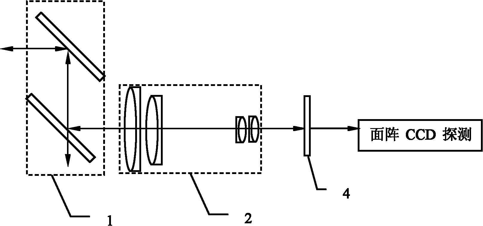
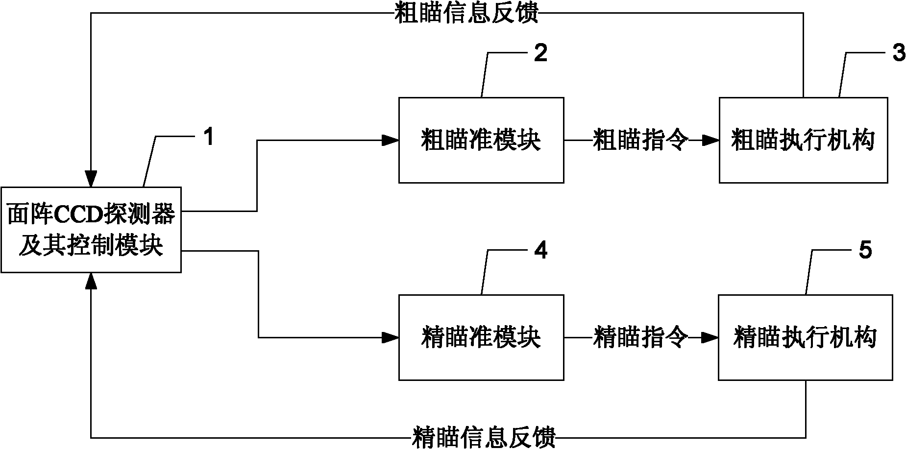
[0035] Specific implementation mode one: the following combination image 3 and Figure 4 Describe this embodiment, the error detection device of the laser communication link beam described in this embodiment includes a rough aiming module 2, a rough aiming actuator 3, a fine aiming module 4 and a fine aiming actuator 5, and it also includes an area array CCD The detector and its control module 1, the output end of the rough aiming command of the area array CCD detector and its control module 1 is connected to the input end of the rough aiming module 2, the output end of the rough aiming module 2 is connected to the input end of the rough aiming actuator 3 Connected, the output end of the rough aiming actuator 3 is connected with the beam coarse aiming correction input end of the area array CCD detector and its control module 1;

[0036] The fine aiming command output end of the area array CCD detector and its control module 1 is connected with the input end of the fine aimin...

specific Embodiment approach 2

[0041] Specific implementation mode two: the following combination Figure 3 to Figure 6 This embodiment is described. This embodiment is based on the beam control method of the laser communication link beam error detection device described in Embodiment 1. The method includes the following steps:

[0042] Step 1. Initialize the area array CCD detector 1-1, determine the aiming center point, and set multiple concentric windows nested sequentially from outside to inside on the area array CCD detector 1-1 with the aiming center point as the reference center: thick Tracking window, fine tracking window and alignment window, the coarse tracking window is a square window with a length of 280 pixels to 350 pixels, the fine tracking window is a square window with a length of 25 pixels to 35 pixels, and the alignment window is a square window with a length of 3 pixels to 6 pixels square window,

[0043] Step 2, judging whether the target imaging spot appears on the area array CCD det...

specific Embodiment approach 3

[0078] Embodiment 3: The difference between this embodiment and Embodiment 2 is that the coarse tracking window in step 1 is a square window with a length of 300 pixels, the fine tracking window is a square window with a length of 30 pixels, and the alignment window is a square window with a length of 4 Pixel square window. Others are the same as the second embodiment.


PUM


Abstract

The invention discloses an error detection device and a control method for laser communication link beams, belongs to the field of optical image processing, and solves the problems that single charge coupled device (CCD) is adopted to perform error detection, the control beams reduce the whole working bandwidth of the system, satellite platform high-frequency vibration cannot be effectively compensated, coarse sighting and fine sighting are easily coupled and the control stability is lower. Coarse sighting instruction output ends of an array CCD detector and a control module thereof are connected with an input end of a coarse sighting module; an output end of the coarse sighting module is connected with an input end of a coarse sighting executing mechanism; an output end of the coarse sighting executing mechanism is connected with beam coarse sighting correction input ends of the array CCD detector and the control module thereof; the fine sighting instruction output ends of the array CCD detector and the control module thereof are connected with an input end of a fine sighting module; an output end of the fine sighting module is connected with an input end of a fine sighting executing mechanism; and an output end of the fine sighting executing mechanism is connected with the beam fine sighting correction input ends of the array CCD detector and the control module thereof.

Description

technical field [0001] The invention relates to an error detection device and a control method for a laser communication link beam, and belongs to the field of optical image processing. Background technique [0002] In space laser communication, acquisition and tracking are key technologies for quickly establishing and stably maintaining communication links. The function corresponding to the detection device is mainly used for real-time detection of the azimuth and elevation angle formed by the incident light beam and the visual axis of the terminal to determine the aiming angle deviation of the terminal. Under the premise of a certain detection accuracy, the work of the coarse aiming mechanism requires the detector to have as large a field of view as possible (miradian scale), while the work of the fine aiming mechanism requires the detector to have as high a frequency response as possible (1kHz above). Therefore, sufficient feedback signals can be provided to the control...

Claims


Application Information

Patent Timeline
Patent Type & Authority Applications(China)
IPC IPC(8): H04B10/08G01B11/26H04B10/07
Inventor 于思源韩琦琦马晶谭立英付森
Owner HARBIN INST OF TECH
Why Eureka
Try Eureka