Protective device for cleaning machine

The technology of a protective device and cleaning machine is applied in the direction of cleaning methods and utensils, chemical instruments and methods, etc., which can solve the problems of motor safety failure, inconvenient wire installation, and large space occupation, and achieve stable and safe lifting, convenient wire installation, The effect of reducing the footprint

Inactive Publication Date: 2011-06-01
TRUKING TECH LTD
View PDF4 Cites 1 Cited by
  • Summary
  • Abstract
  • Description
  • Claims
  • Application Information

AI Technical Summary

Problems solved by technology

However, when the screw rod drives the protective cover to rise, the electric wire passing through the screw rod will rise together, which brings inconvenience to the installation of the electric wire
On the other hand, when cleaning glass bottles, the humidity inside the protective cover is high, and the motor in the protective cover is prone to safety failures, which will affect the normal operation of the cleaning machine and endanger the personal safety of the operator.
Moreover, since the guide mechanism is connected to the outer side of the protective cover, most of it is outside the protective cover, so its space occupation is large, the structure is not compact, and the lifting and guiding stability of the protective cover is not good, and the force on the protective cover is uneven. , easily lead to tilt

Method used


Image

  • Protective device for cleaning machine
  • Protective device for cleaning machine
  • Protective device for cleaning machine

Examples


Embodiment Construction

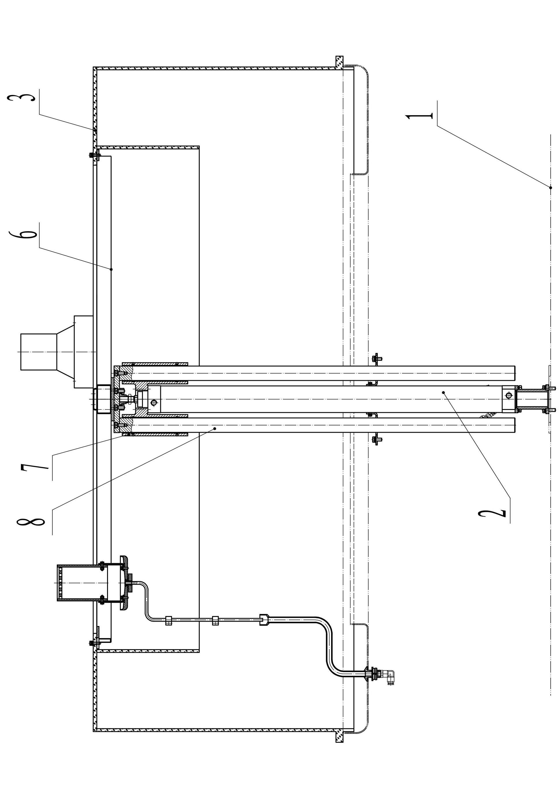
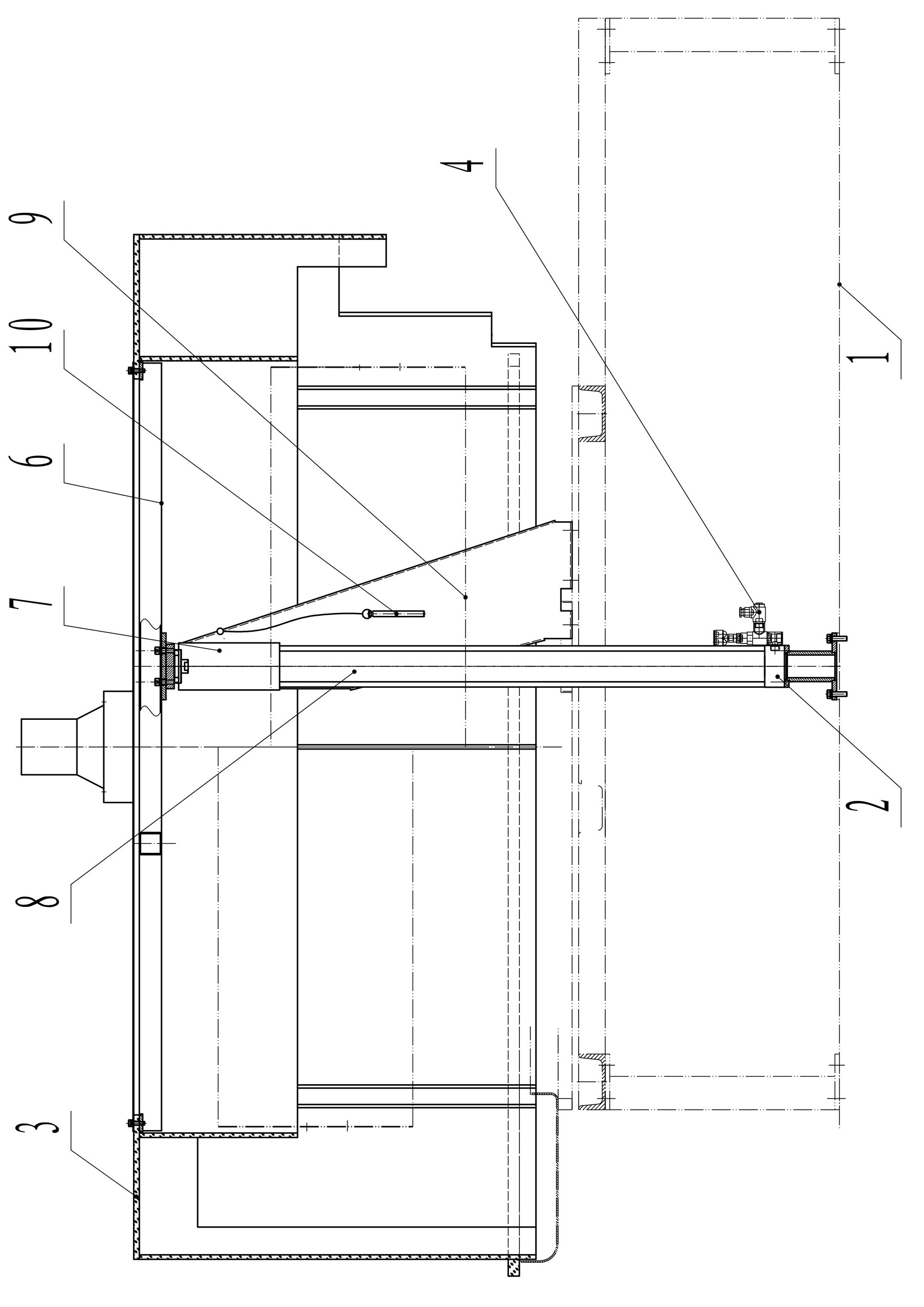
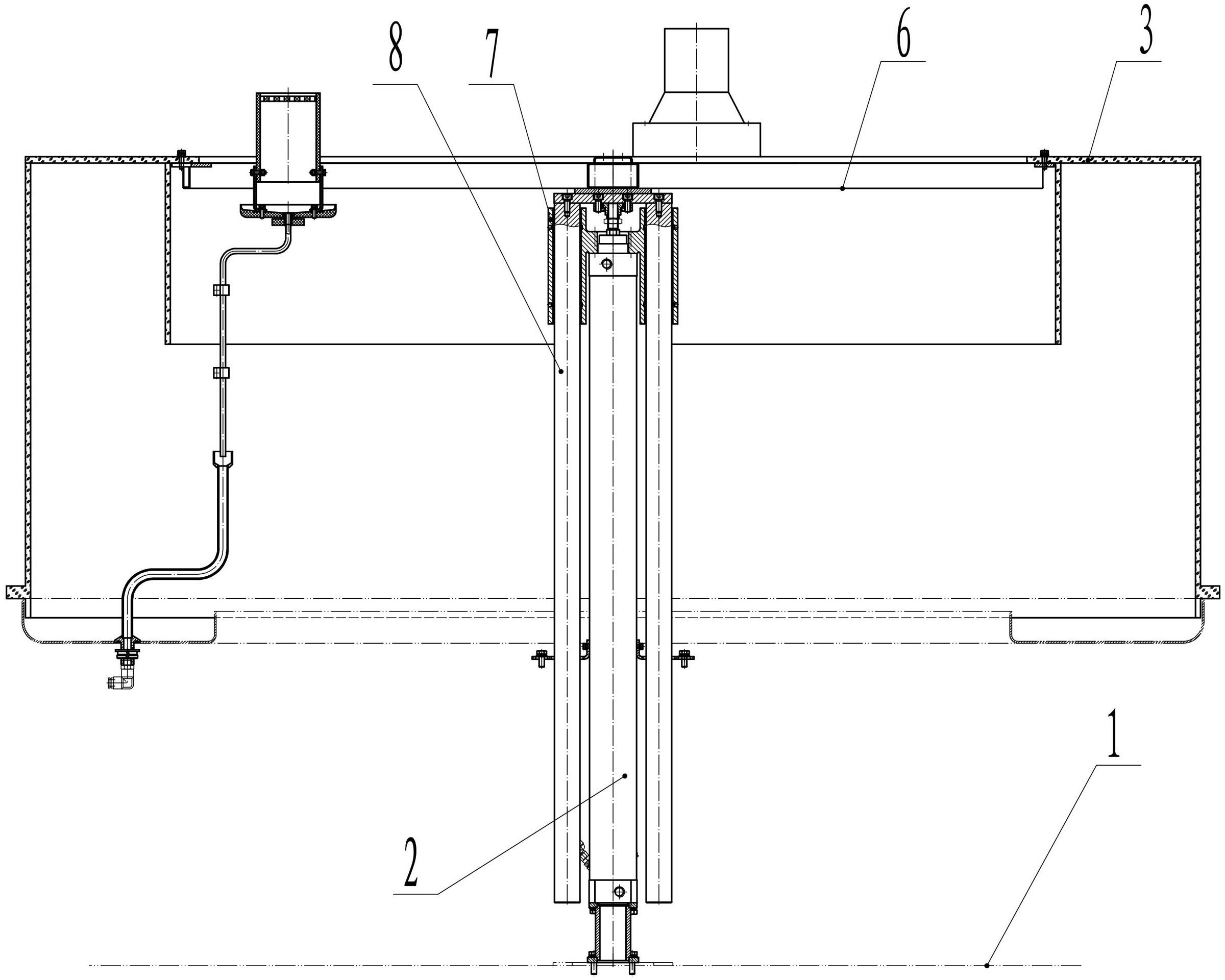
[0017] The present invention will be further described below in combination with specific embodiments and accompanying drawings.

[0018] like figure 1 and figure 2 As shown, the protective device for washing machine of the present invention includes a frame 1, a protective cover 3 and a drive cylinder installed on the frame 1 for driving the protective cover 3 to lift, and the protective cover 3 is connected to the telescopic end of the drive cylinder. More than one guide mechanism is arranged along the peripheral side of the cylinder outer wall of the driving cylinder. The protective cover 3 lifts under the driving of the drive cylinder and the stable guidance of the guide mechanism, so as to realize the setting and opening of the cleaning machine. Since the guide mechanism is installed close to the drive cylinder, most of it is in the protective cover, which can effectively save space, reduce the occupied area, and make the structure more compact. At the same time, the...


PUM


Abstract

The invention discloses a protective device for a cleaning machine, comprising a stand, a protective cover and a driving tank which is arranged on the stand and used for driving the protective cover to lift and fall; the protective cover is connected to an expandable end of the driving tank; and more than one guiding mechanism is arranged along the peripheral side of the outer wall of the tank body of the driving tank. The protective device for the cleaning machine, provided by the invention, has the advantages of simple and compact structure, low cost, convenience for installation, good movement stability as well as safety and reliability in working.

Description

technical field [0001] The invention relates to the field of packaging machinery and equipment for food and medicine, in particular to a cleaning machine for packaging containers. Background technique [0002] At present, in order to ensure the air cleanliness of the cleaning machine when cleaning glass bottles, it is generally necessary to cover the cleaning mechanism in a protective device. In the existing protective device, the protective cover is fixed on the screw rod, and the outer edge of the protective cover is connected with a guide mechanism. The motor drives the screw up and down to realize the opening or setting of the protective cover. This kind of structure is because the stroke of screw rod is longer on the one hand, and in order to guarantee the lifting stroke of screw rod, motor is generally connected to the middle and upper part of screw rod by gear, and when protective cover is arranged on cleaning mechanism, motor can be in protective cover. In order to...

Claims


Application Information

Patent Timeline
Patent Type & Authority Applications(China)
IPC IPC(8): B08B13/00
Inventor 阳文录邱永谋姜晓明刘振李鹏程唐岳
Owner TRUKING TECH LTD
Why Eureka
Try Eureka