
Mould for forming multi-channel filter element and method for forming intermetallic compound multi-channel filter element

A multi-channel and mold technology, applied in the field of multi-channel filter element molding, can solve the problems of extremely high mold pressure, mandrel cannot be demolded, and structure is not enough to meet the requirements, so as to improve the overall quality and ensure the position degree.

Active Publication Date: 2011-06-01
CHENGDU INTERMENT TECH
View PDF5 Cites 28 Cited by
  • Summary
  • Abstract
  • Description
  • Claims
  • Application Information

AI Technical Summary

Problems solved by technology

However, the above structure alone is not enough to satisfy the requirement
Because the pressure medium will exert extremely high pressure on the mold during isostatic pressing, so each slender mandrel will be squeezed by the surrounding powder and bend, resulting in the mandrel not being able to be demolded
Since this problem cannot be solved at present, it also limits the production of multi-channel filter elements of intermetallic compounds

Method used


Image

  • Mould for forming multi-channel filter element and method for forming intermetallic compound multi-channel filter element
  • Mould for forming multi-channel filter element and method for forming intermetallic compound multi-channel filter element
  • Mould for forming multi-channel filter element and method for forming intermetallic compound multi-channel filter element

Examples


Embodiment Construction

[0026] The present invention will be further described below in conjunction with the accompanying drawings.

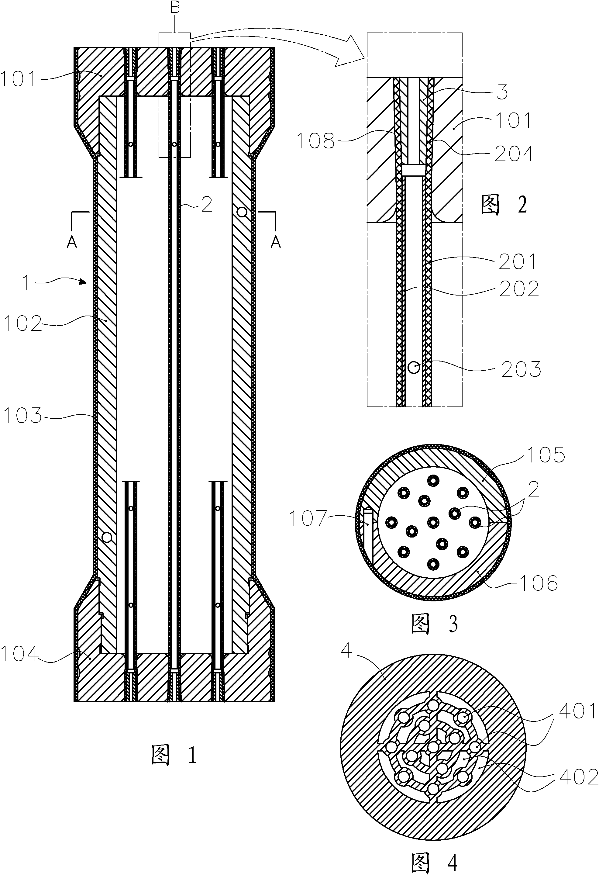
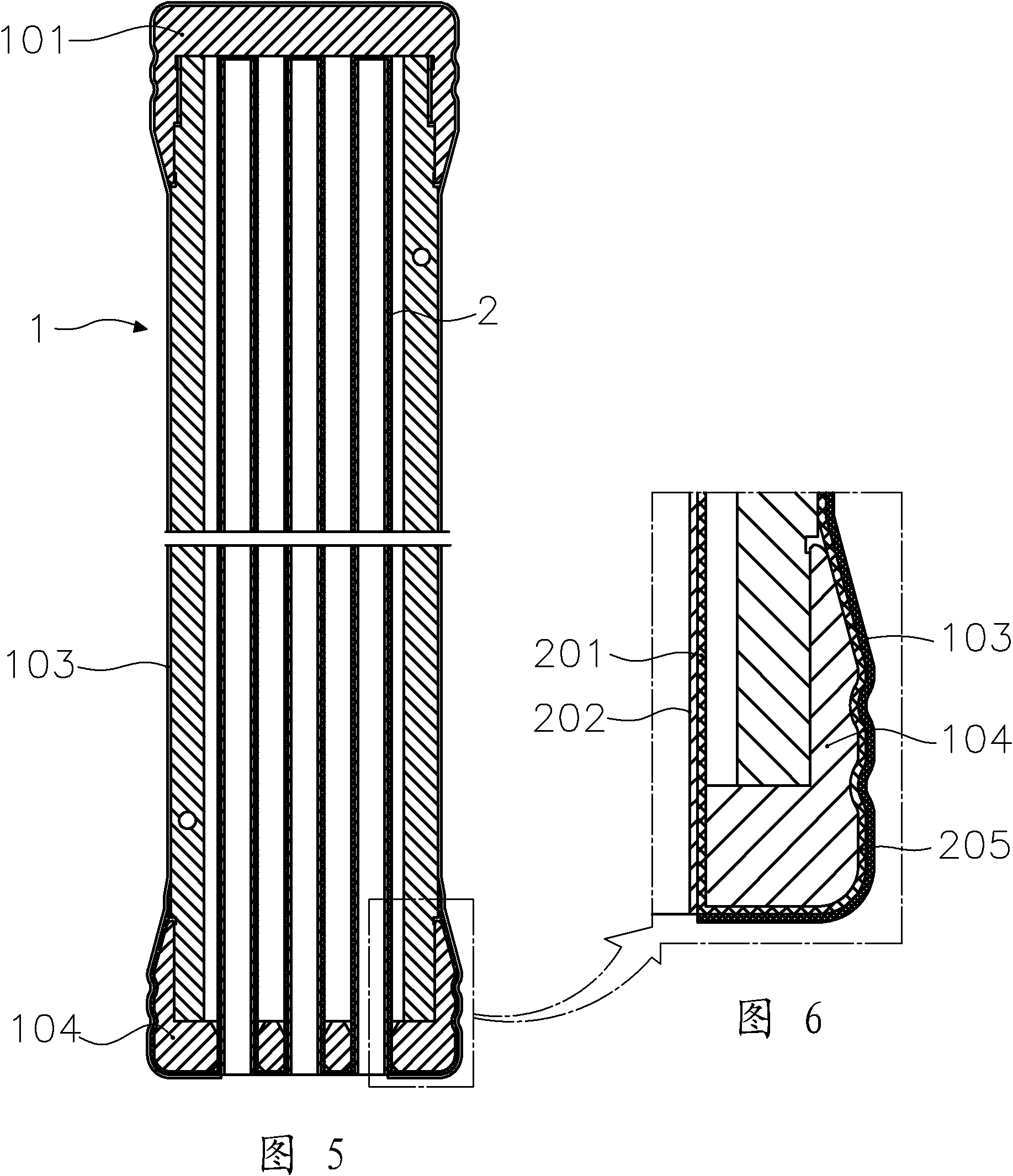
[0027] like Figures 1 to 3 shown. The outer mold 1 includes a rigid sleeve 102 formed by two petal-shaped pieces 105 and 106 that can be separated and fastened together, and a front end cover 101 and a rear end cover 104 respectively installed on the front and rear ends of the rigid sleeve 102; each mandrel 2 is supported by a support tube. 202 and an elastic sleeve 201 sleeved on the support tube 202, the end of each mandrel 2 has an elastic sleeve extension 204 axially extended from the port of the support tube 202 by the elastic sleeve 201; Both ends are inserted into the corresponding positioning holes 108 on the front end cover 101 and the rear end cover 104 respectively, and the plug 3 is inserted into the elastic sleeve extension section 204 to expand the elastic sleeve extension section 204 in the positioning hole 108 and the plug 3; the plug 3 is a structur...


PUM


Abstract

The invention discloses a mould which is easy to demould a core rod and used for forming a multi-channel filter element. The mould comprises an outer mould and multiple core rods mounted in the outer mould, wherein each core rod is composed of a support tube and an elastic sleeve sleeved on the support tube; multiple through holes are formed on the wall, on which the elastic sleeve is sleeved, ofeach support tube; and at least one end of each core rod is an open end communicated with the exterior of the mould. The support tubes can support the core rods so as to accurately position the core rods in the outer mould, thereby basically ensuring the true position after inner bores of a filter element are formed and improving the entire quality of the filter element; when the elastic sleeve is formed, the elastic sleeve extrudes powder filled between the outer mould and the core rods from inside to outside so as to carry out compression moulding on the powder; and during demoulding, the elastic sleeve retracts so as to demould the core rods. The invention also discloses a method for forming an intermetallic compound multi-channel filter element, wherein an intermetallic compound material filled in the cavity of the mould is pressed into the multi-channel filter element by use of an isostatic pressing technology. By utilizing the method, the cold isostatic pressing manufacturing ofthe intermetallic compound multi-channel filter element is achieved.

Description

technical field [0001] The invention relates to a molding technology of a multi-channel filter element. Background technique [0002] There are currently no multi-channel filters made of intermetallic compounds on the market. The reason is that with the existing filter element manufacturing technology, it is only possible to use the isostatic pressing method to make the intermetallic compound into the multi-channel filter element, and there is no mold suitable for isostatic pressing of the multi-channel filter element. Practically speaking, if a person skilled in the art wants to develop a mold for isostatic pressing of a multi-channel filter element, the mold is designed to include an outer mold and a plurality of core rods installed in the outer mold. Should be obvious. However, the above structure alone is not sufficient. Because the pressure medium exerts extremely high pressure on the mold during isostatic pressing, each slender mandrel will be squeezed by the surrou...

Claims


Application Information

Patent Timeline
IPC IPC(8): B22F3/03B22F5/10
Inventor 贺跃辉高麟徐进辉汪涛徐君亮蒋敏
Owner CHENGDU INTERMENT TECH
Learn More