
Method for testing radar scattering cross section

A technology of radar scattering cross section and scattering cross section, which is applied in the direction of radio wave measurement systems and instruments, and can solve problems such as difficulty in meeting high frequency requirements

Active Publication Date: 2013-09-18
CHINA SHIP DEV & DESIGN CENT
View PDF0 Cites 0 Cited by
  • Summary
  • Abstract
  • Description
  • Claims
  • Application Information

AI Technical Summary

Problems solved by technology

However, there is a key technical problem that needs to be solved urgently in the model test: the scaling principle requires the test equipment to have a very high test frequency, which requires the use of equipment with a high test frequency, and the traditional electromagnetic wave equipment is difficult to meet this requirement. high frequency demand

Method used


Image

  • Method for testing radar scattering cross section
  • Method for testing radar scattering cross section
  • Method for testing radar scattering cross section

Examples


Embodiment Construction

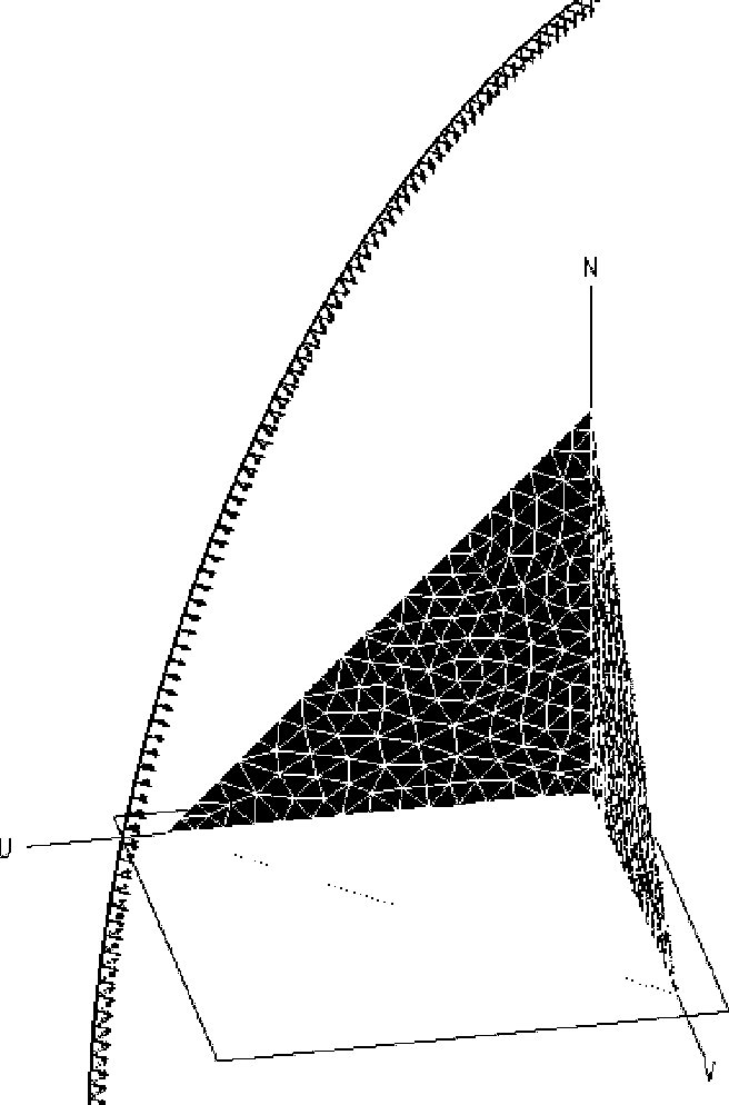
[0033] In this embodiment, a triangular corner reflector is taken as an example for detailed description. The model information is as follows: the side length is 0.1m, and the incident direction is as follows figure 1 shown. Suppose the operating frequency of the microwave radar is 10GHz, and the operating frequency of the lidar is 10000GHz.

[0034] Firstly, the laser radar is selected for the radar scattering interface test (that is, the RCS test), and the laser radar scattering cross-section curve of the triangular corner reflector is obtained, as shown in figure 2 Shown (for ease of display, the unit of the curve has been converted to dB);

[0035] According to the operating frequency of microwave radar and lidar, M 2 = f L / f R = 1000;

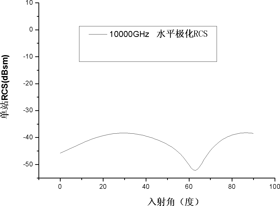
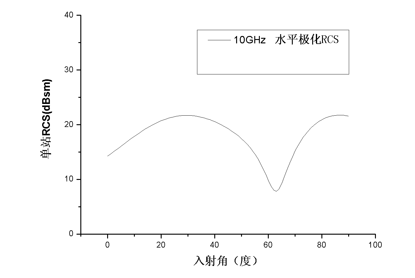
[0036] Will M 2 =1000 is substituted into the conversion equation of the laser radar scattering cross section and the microwave radar scattering cross section, and the microwave radar scattering cross section curve of the triangul...


PUM


Abstract

The invention provides a method for testing a radar scattering cross section, which comprises the following steps: 1) selecting and using a laser radar to test a target scattering cross section; 2) listing the definition of the laser radar scattering cross section and the definition of a microwave radar scattering cross section; 3) comparing the definition of the laser radar scattering cross section with the definition of the microwave radar scattering cross section, so as to obtain a relevance expression between the laser radar scattering cross section and the microwave radar scattering cross section; 4) according to the relevance expression, obtaining a transfer equation between the laser radar scattering cross section and the microwave radar scattering cross section; and 5) according to the transfer equation, obtaining a microwave radar scattering cross section curve. According to the invention, the traditional microwave radar is replaced by the laser radar, and the target microwave radar scattering cross section curve can be obtained under the condition of the known frequency scale factor of the laser radar and the microwave radar and the known target laser radar scattering cross section.

Description

technical field [0001] The invention belongs to the field of electromagnetic compatibility research. Background technique [0002] Since the electromagnetic scattering characteristics of the target are closely related to the target structure, a large amount of design work is completed in the target technology design stage, and the design effect can only be known after the actual measurement after the target is built and formed. This kind of design is out of touch with the effect test Phenomena seriously restrict the progress of technology. [0003] The best way to change this situation is to use scale model testing technology to test and check the electromagnetic scattering design effect of the target in the design stage. Designers can modify or redesign the drawings according to the test results until they are satisfied. However, there is a key technical problem that needs to be solved urgently in the model test: the scaling principle requires the test equipment to have a ...

Claims


Application Information

Patent Timeline
Patent Type & Authority Patents(China)
IPC IPC(8): G01S7/41
Inventor 方重华宋东安谭辉张崎喻菁
Owner CHINA SHIP DEV & DESIGN CENT
Learn More