Commutator motor

A commutator and motor technology, which is applied in the field of commutator motors, can solve the problems of brush contact area reduction, narrow space distance, spark generation, etc., and achieve the effect of improving rectification performance, improving rectification performance, and improving electrification performance

Inactive Publication Date: 2011-06-01
SANYO ELECTRIC CO LTD +1
View PDF8 Cites 2 Cited by
  • Summary
  • Abstract
  • Description
  • Claims
  • Application Information

AI Technical Summary

Problems solved by technology

[0006] The structure of the brush proposed in Patent Document 1 cuts off both widthwise end edges of the front end surface (circumferential contact surface) of the brush, so the contact area of ​​the brush with respect to the commutator is greatly reduced, and there is a problem that the current density increases. Risk of bad rectification
In addition, in the proposal of Patent Document 1, since both ends of the brush in the width direction are cut at right angles to ...

Method used


Image

  • Commutator motor
  • Commutator motor
  • Commutator motor

Examples


Embodiment Construction

[0052] Hereinafter, embodiments of the present invention will be specifically described with reference to the drawings.

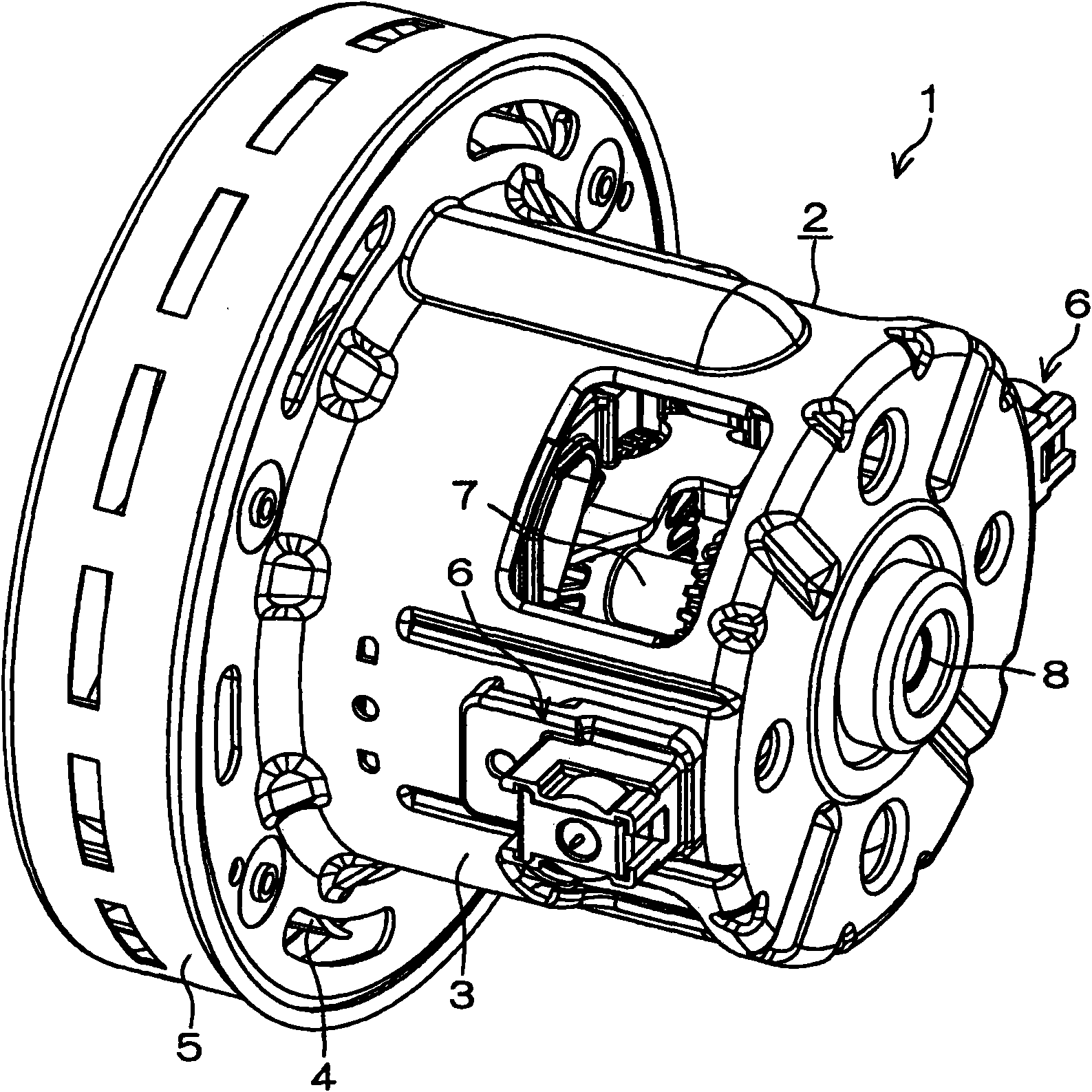
[0053] figure 1 It is a perspective view of the electric blower 1 of one embodiment seen from obliquely rearward.

[0054] A commutator motor according to one embodiment of the present invention is incorporated in the blower 1 .

[0055] exist figure 1 In the figure, 2 represents the case 2 which forms the outer shape of the electric blower 1, and this case 2 also serves as the case of the commutator motor. Case 2 includes bracket 3 covering the outside of the motor, and fan case 5 covering the outside of blower blade 4 .

[0056] A brush unit 6 is attached to the bracket 3 . Part of the brush unit 6 protrudes outward from the bracket 3 . A mounting hole for the brush unit 6 is formed in the bracket 3 , and the brush unit 6 is configured to be fitted into the mounting hole from the outside of the bracket 3 to be mounted.

[0057] In addition, in figu...


PUM


Abstract

The invention provides a commutator motor, wherein the contact structure of a commutator and a brush is improved.The commutator (12) is equipped with a plurality of commutator sheets (121) and the commutator sheets are respectively in contact with the front end face (26F) of the brush (26) along with the rotation of a rotor(13).The front end face (26F) of the brush (26) is a concave curved surface formed along part of the periphery of the commutator sheets (121) in the rotational direction of the rotor (13).The end edge of the concave curved surface at the downstream of the rotational direction of the rotor (13) is chamfered to form an inclined tangent plane (35).The width of the rotational direction of the front end face (26F) is narrowed by the inclined tangent plane (35), thereby facilitating the so-called whole surface contact between the front end face of the brush and the commentator.In addition, the inclined tangent plane is cut along the departure direction from the surface of the commentator, which ensures the spatial distance between the cutting face and the commentator.As a result, sparks are avoided at the downstream side of the rotational direction of the front end face of the brush.

Description

technical field [0001] The present invention relates to a commutator motor, and more particularly to a commutator motor used in an electric blower built in an electric vacuum cleaner. Background technique [0002] The commutator motor includes a rotor having a commutator and brushes that are in circumferential contact with the commutator. One end of the stator winding is connected to the brush, and by sequentially switching the segments of the commutator in contact with the brush, the current supplied to the stator winding is switched to rotate the field magnetic flux. [0003] In a commutator motor, good contact between the commutator and the brush is required, both electrical and mechanical, and conventionally, proposals have been made to make good contact between the brush and the commutator. [0004] For example, in Patent Document 1, it is proposed that by cutting the width direction (the so-called width direction refers to the direction along the direction of rotation...

Claims


Application Information

Patent Timeline
IPC IPC(8): H02K23/00
Inventor 樽谷隆夫
Owner SANYO ELECTRIC CO LTD
Why Eureka
Try Eureka