Power Controller and Vehicle Equipped with Power Controller

a technology of power controller and power controller, which is applied in the direction of gas pressure propulsion mounting, electric devices, and conversion with intermediate conversion to dc, can solve the problem of inability to control the charge mode, and achieve the effect of reducing the number of additional components

Inactive Publication Date: 2009-03-12
TOYOTA JIDOSHA KK
View PDF10 Cites 47 Cited by
  • Summary
  • Abstract
  • Description
  • Claims
  • Application Information

AI Technical Summary

Benefits of technology

[0033]Further, according to the present invention, for charging the power storage device from the AC power supply and for feeding power from the power storage device to the AC power supply, poly-phase windings of the first and second AC rotating electrical machines an

Problems solved by technology

Further, while the induction motors MA and MB are controlled for d

Method used


Image

  • Power Controller and Vehicle Equipped with Power Controller
  • Power Controller and Vehicle Equipped with Power Controller
  • Power Controller and Vehicle Equipped with Power Controller

Examples


embodiment 1

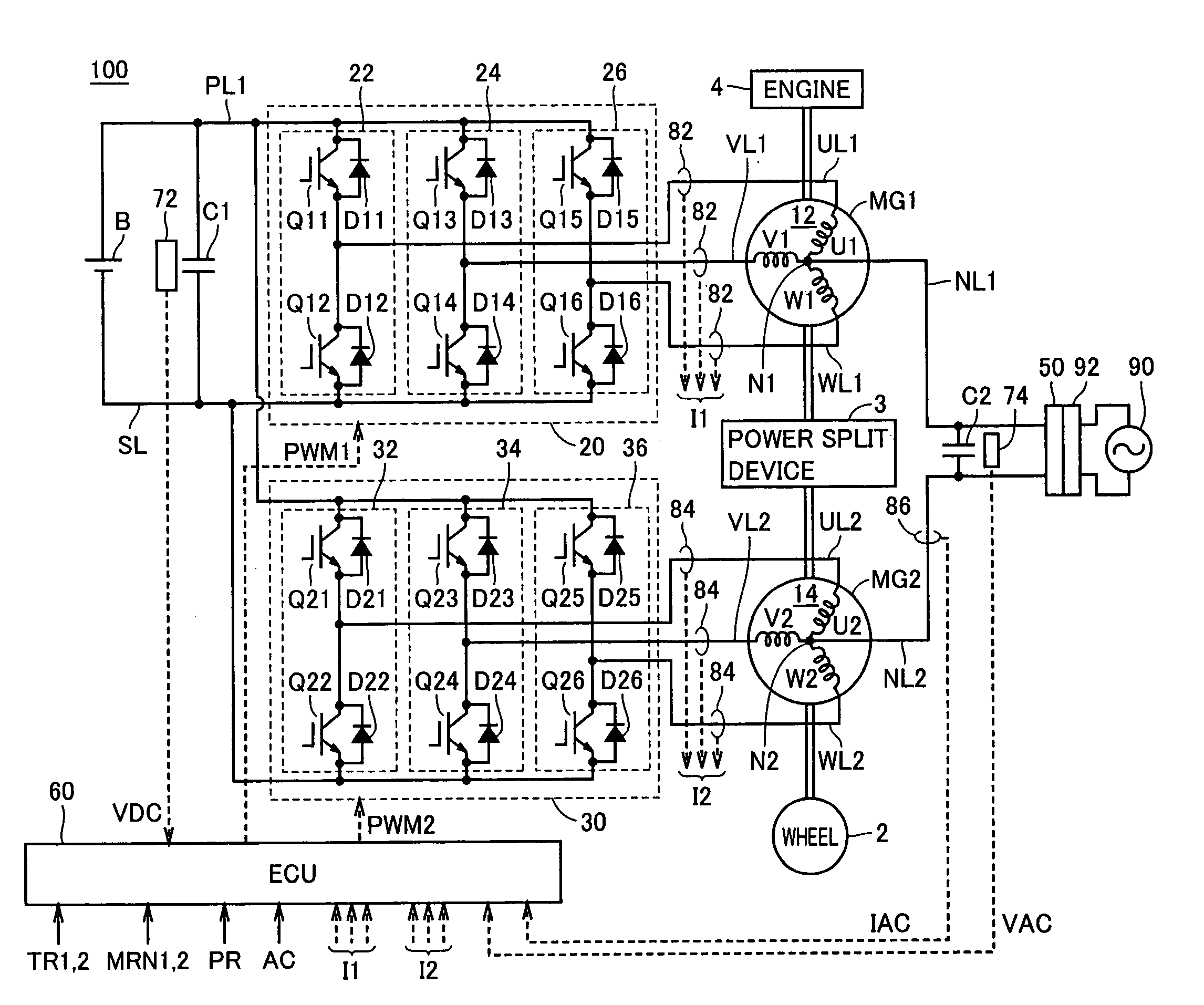
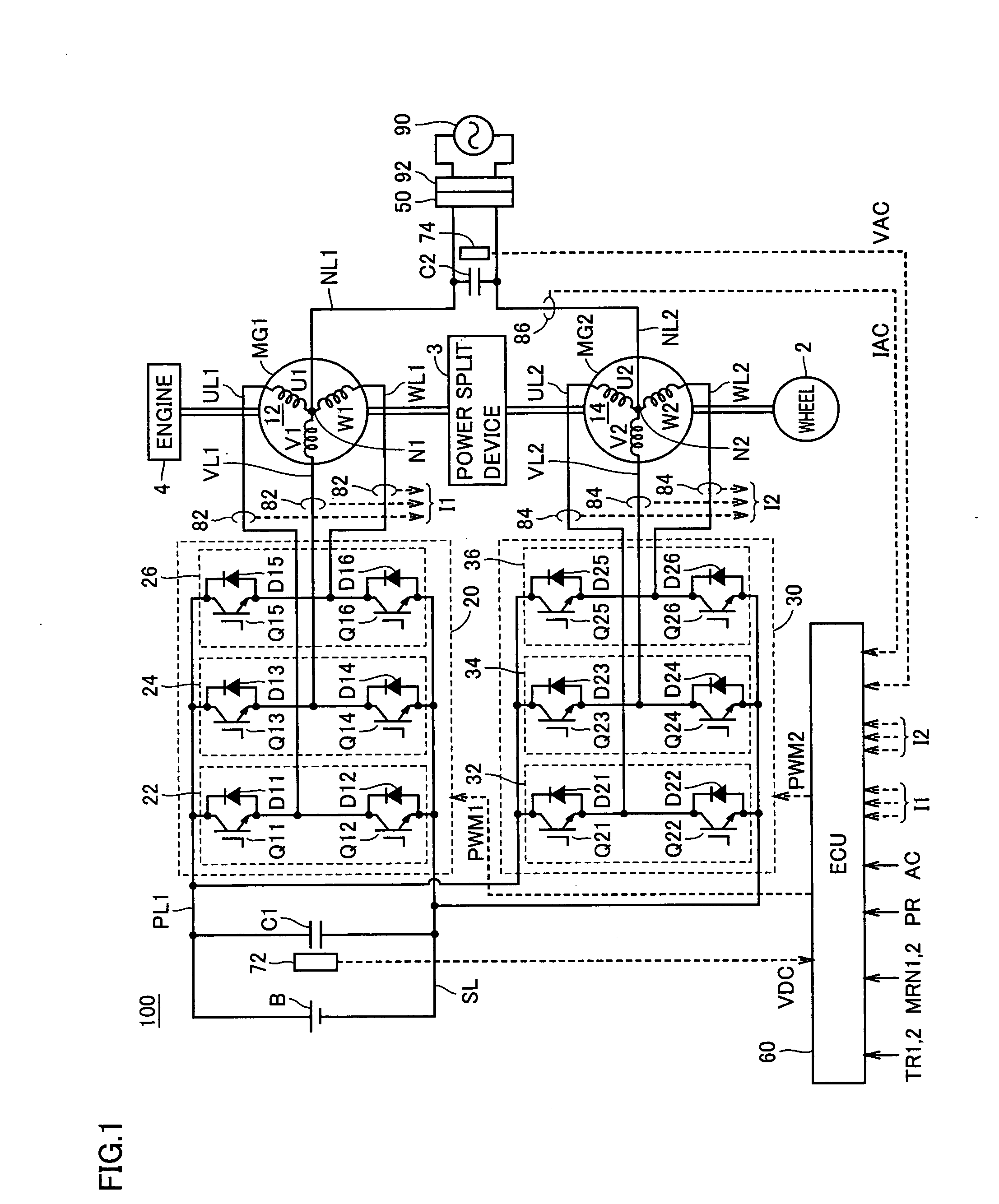
[0065]FIG. 1 is an overall block diagram of the hybrid vehicle shown as an example of the vehicle in accordance with Embodiment 1 of the present invention. Referring to FIG. 1, a hybrid vehicle 100 includes an engine 4, motor generators MG1 and MG2, a power split device 3, and wheels 2. Hybrid vehicle 100 further includes a power storage device B, inverters 20 and 30, and an ECU (Electronic Control Unit) 60.

[0066]Hybrid vehicle 100 further includes a capacitor C1, a power line PL1, a ground line SL, U-phase lines UL1 and UL2, V-phase lines VL1 and VL2, W-phase lines WL1 and WL2, a voltage sensor 72, and current sensors 82 and 84. Hybrid vehicle 100 further includes power lines NL1 and NL2, a connector 50, a capacitor C2, a voltage sensor 74, and a current sensor 86.

[0067]Hybrid vehicle 100 runs using engine 4 and motor generator MG2 as power sources. Power split device 3 is coupled to engine 4 and to motor generators MG1 and MG2, and distributes power among these. By way of example,...

embodiment 2

[0126]In Embodiment 1, only the inverter 20 (or 30) is PWM-operated based on zero-phase command voltage E0, while in Embodiment 2, both inverters 20 and 30 are PWM-operated.

[0127]Embodiment 2 differs from Embodiment 1 in the configuration of inverter control unit, and except for this point, it is the same as Embodiment 1.

[0128]FIG. 15 is a detailed functional block diagram of the inverter control unit in accordance with Embodiment 2. Referring to FIG. 15, inverter control unit 64A corresponds to inverter control unit 64 of Embodiment 1 shown in FIG. 4, and it additionally includes multiplying units 126 and 128 and a subtracting unit 130.

[0129]Multiplying unit 126 multiplies zero-phase command voltage E0 from current control unit 118 by ½, and outputs the result of operation to adding unit 120. Adding unit 120 adds the output from multiplying unit 126 to the command voltage of each phase from phase voltage operating unit 112 for motor control, and outputs the result of operation to P...

embodiment 3

[0150]In order for the amount of control to follow the target input without steady deviation, it is necessary that a closed loop of the control system contain a target input generation model (internal model principle). Therefore, in Embodiment 3, a configuration is disclosed in which, utilizing the fact that command current IR is a sinusoidal function, a model of command current IR (internal model) is included in the closed loop of current control system.

[0151]Embodiment 3 is different from Embodiment 1 or 2 in the configuration of current control unit in inverter control unit and, except for this point, the configuration is the same as that of Embodiment 1 or 2.

[0152]FIG. 19 is a control block diagram representing a configuration of the current control unit in accordance with Embodiment 3. Referring to FIG. 19, current control unit 118A includes a PI control unit 202, an internal model compensating unit 204 and an adding unit 206.

[0153]PI control unit 202 performs a proportional in...


PUM


Abstract

An ECU detects an effective value and phase of a voltage from a commercial power supply, based on a voltage from a voltage sensor. Further, ECU generates a command current, which is a command value of current caused to flow through power lines and in-phase with the voltage of the commercial power supply, based on the detected effective value and the phase and on a charge/discharge power command value for a power storage device. Then, ECU controls zero-phase voltage of inverters based on the generated command current.

Description

TECHNICAL FIELD[0001]The present invention relates to a power controller and a vehicle equipped with the controller and, particularly, it relates to a power controller exchanging electric power between a commercial power supply and a power storage device mounted on a vehicle, as well as to a vehicle equipped with the power controller.BACKGROUND ART[0002]Japanese Patent Laying-Open No. 4-295202 discloses a motor drive capable of exchanging electric power between an AC power supply outside a vehicle and a DC power supply provided in the vehicle. The motor drive includes a battery, inverters IA and IB, induction motors MA and MB, and a control unit. Induction motors MA and MB include Y-connected windings CA and CB, respectively. To neutral points NA and NB of windings CA and CB, an input / output port is connected through an EMI filter. Inverters IA and IB are provided corresponding to induction motors MA and MB, respectively, and connected to windings CA and CB, respectively. Inverters ...

Claims


Application Information

Patent Timeline
IPC IPC(8): H02M7/68B60L50/15B60L50/16H02J3/32H02J3/38H02J7/00
CPCB60K1/02B60L11/1842B60K6/445B60L11/123B60L11/14B60L11/1814B60L11/1816B60L11/185B60L15/007B60L2210/20B60L2220/12B60L2220/14B60L2220/54H02J3/32H02J7/0044H02J7/022Y02T10/6217Y02T10/6239Y02T10/6269Y02T10/641Y02T10/644Y02T10/646Y02T10/7005Y02T10/7077Y02T10/725Y02T90/121Y02T90/127Y02T90/128Y02T90/14Y04S10/126Y02E60/721Y02T10/648B60K6/365Y02P80/10Y02T10/7072B60L53/14B60L50/61B60L50/16B60L53/24B60L55/00B60L53/11H02J7/02H02J2207/20Y02E60/00Y02T10/62Y02T10/64Y02T10/72Y02T10/70H02J3/322Y02T10/92H02M7/02H02J7/00Y02T90/12
Inventor OYOBE, HICHIROSAIISHIKAWA, TETSUHIROWATANABE, YOSHITOSHIASANO, KATSUHIRO
Owner TOYOTA JIDOSHA KK
Why Eureka
Try Eureka