Camber angle changing mechanism

A camber angle, variable technology, applied in the direction of steering mechanism, elastic suspension, cantilever installed on the pivot, etc., can solve the problems of fuel consumption rate deterioration, space requirement, increased weight, etc., to achieve fewer parts and light weight The effect of low cost and strong resistance to external forces

Inactive Publication Date: 2013-05-29
EQUOS RES
View PDF1 Cites 4 Cited by
  • Summary
  • Abstract
  • Description
  • Claims
  • Application Information

AI Technical Summary

Problems solved by technology

[0004] However, in mechanisms that generally use actuators, power is always required to maintain a predetermined camber angle, so efficiency may decrease and fuel consumption may deteriorate
In addition, if a stop mechanism that stops the operation of the actuator at a predetermined position is provided, additional space is required and weight increases

Method used


Image

  • Camber angle changing mechanism
  • Camber angle changing mechanism
  • Camber angle changing mechanism

Examples


Embodiment Construction

[0053] Hereinafter, embodiments of the present invention will be described in detail with reference to the drawings.

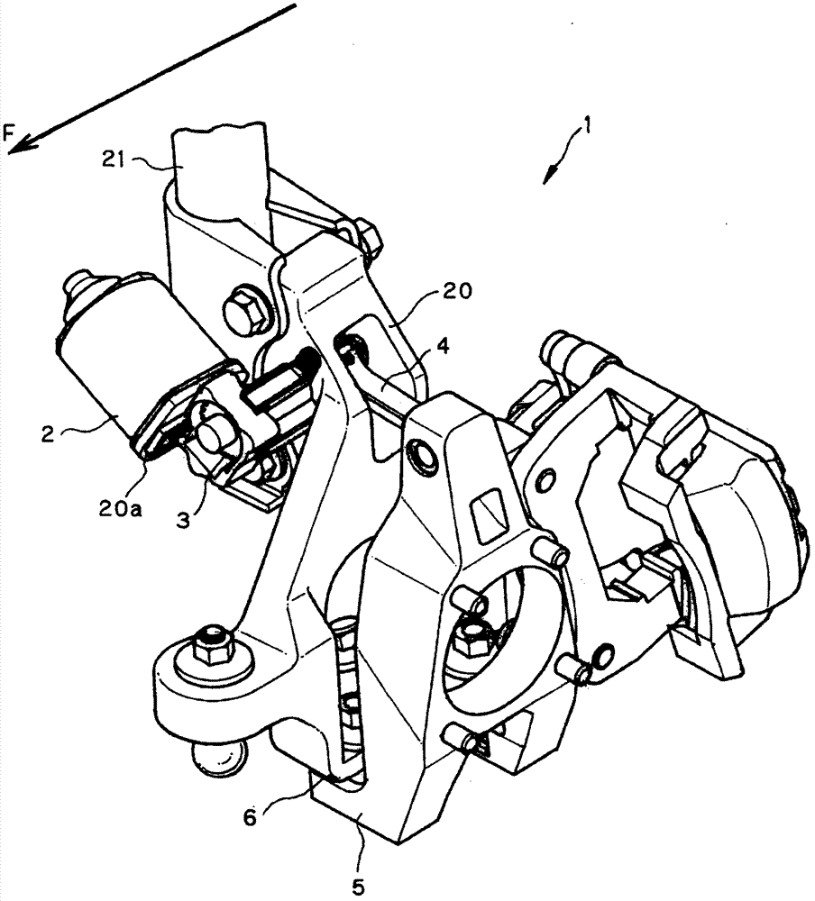
[0054] figure 1 It is a perspective view showing the camber angle variable mechanism 1 of the first embodiment seen from the upper front. figure 2 It is a figure which shows the camber angle variable mechanism 1 of 1st Embodiment seen from the rear. Among them, in figure 2 In FIG. 1 , the support rod and the steering knuckle are omitted for easy observation of the camber angle variable mechanism 1 .

[0055] In addition, front and rear here correspond to the front and rear directions of the vehicle, and arrow F in the figure indicates the front. In addition, the vehicle width direction refers to a direction perpendicular to the front-rear direction of the vehicle (the same applies hereinafter).

[0056] exist figure 1 and figure 2 Among them, 1 represents the camber angle variable mechanism, 2 represents the motor, 3 represents the worm wheel as the...


PUM


Abstract

A camber angle changing mechanism (1) for changing the camber angle of a wheel (30) relative to a vehicle body. The camber angle changing mechanism (1) is provided with a base member (20) connected to the vehicle body side, a motor (2) provided to the base member (20) and generating rotational driving force, a power transmitting mechanism (3, 130, 230, 330, 430, 530) rotating on a rotation axis and transmitting the driving force of the motor (2), a transmitting member (4) connected to the power transmitting mechanism (3, 130, 230, 330, 430, 530) through a first connecting section (34), a movable member (5) for rotatably supporting the wheel (30), connected to the transmitting member (4) through a second connecting member (45), and changing the camber angle of the wheel (30) by being pivoted relative to the base member (20) by the driving force of the motor (2) transmitted from the transmitting member (4), and a switching means (2) for switching between a first state in which the second connecting section (45), the first connecting section (34), and a gear rotation axis (C) are rectilinearly arranged in that order from the wheel (30) side and a second state in which the second connecting section (45), the gear rotation axis (C), and the first connecting section (34) are rectilinearly arranged in that order from the wheel (30) side.

Description

technical field [0001] The present invention relates to a camber angle variable mechanism capable of changing the camber angle of a wheel with a simple structure. Background technique [0002] In the past there existed a device such as Figure 28 As shown, in order to be able to control the camber and toe angle (tou) of each wheel through the actuator, the device has: a ball joint 533, which supports the axle 532 supporting the wheel at one point relative to the vehicle body; the first and The second actuators 534, 535 support two points in the front-rear direction of the vehicle on the upper side or lower side of the support point supported by the ball joint 533 on the shaft 532, and make the support point of the two points in the displacement in the vehicle width direction; the control mechanism, which controls the first and second actuators 534, 535, changes the wheel toe angle and Or, the camber of the wheel is changed by displacing the supporting points of the above tw...

Claims


Application Information

Patent Timeline
Patent Type & Authority Patents(China)
IPC IPC(8): B60G17/015B60G7/00
CPCB60G2204/421B60G2202/42B60G7/006B60G7/008B60G2204/4193B60G2200/46B60G2204/42B60G21/007B60G2200/142B62D17/00B60G2204/416B60G2204/62B60G2206/50
Inventor 堀口宗久水野晃安藤正夫长谷部正广神谷齐沟手信一朗
Owner EQUOS RES
Why Eureka
Try Eureka