
Ferro-magnetic quenching metal strip coiling device

A coiling device and cold metal technology, applied in the field of quenched metal strip manufacturing, can solve problems such as strip tearing, insufficient effective bonding area, and distortion

Inactive Publication Date: 2015-04-29
滨州益谦非晶金属材料科技有限公司
View PDF7 Cites 0 Cited by
  • Summary
  • Abstract
  • Description
  • Claims
  • Application Information

AI Technical Summary

Problems solved by technology

[0011] The first technical problem to be solved by the present invention is that in the prior art, the double-sided adhesive bonding technology is used to grab the quenched metal strip, and its effective bonding area is not enough; the negative pressure method is used to coil the quenched metal strip, which is easy to Due to the effect of the gravity of the material, the movement track of the strip is erratic, so that the coiling wheel cannot adsorb both sides of the strip at the same time, which will easily cause the steel strip to be twisted, and finally leave the coiling wheel or even twist; thus providing a Ferromagnetic quenched metal strip grabbing device with sufficient effective bonding area, which can ensure that the strip is not twisted and has extremely high flatness during the grabbing process
[0012] The second technical problem to be solved by the present invention is that in the prior art, the negative pressure method is used to coil the amorphous material. Due to the erratic strip material, it is easy to make the amorphous material be wound around once and for all when it is adsorbed on the coiling wheel. The position is not neat and consistent, which can easily lead to tearing of the strip; and then provide a ferromagnetic quenched metal strip grabbing device that can ensure the regularity of the strip coiling and winding during the grabbing and coiling process

Method used


Image

  • Ferro-magnetic quenching metal strip coiling device
  • Ferro-magnetic quenching metal strip coiling device
  • Ferro-magnetic quenching metal strip coiling device

Examples


Embodiment Construction

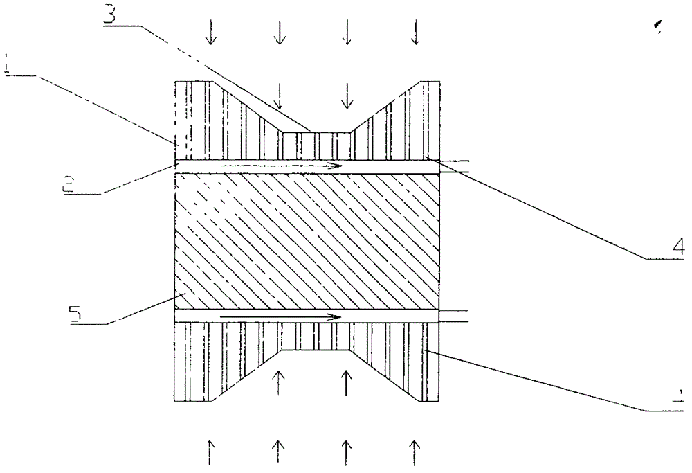
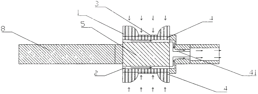
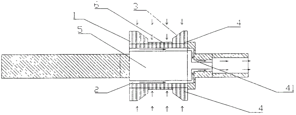
[0042] like figure 1 Shown is the ferromagnetic quenching metal strip coiling device of the present invention, the device includes a housing 1, an axially opened cavity is provided inside the housing 1, and the housing 1 can be powered Driven to rotate continuously in the axial direction, the power drive device can be selected as a motor or the like. A first groove 3 is provided on the housing 1 along the circumferential direction of the housing 1, and a circle is arranged along the circumferential direction, that is, in the axial direction. The width of the bottom end of the first groove 3 is greater than or equal to the The width of the quenched metal strip, the width of the opening end of the first groove 3 is greater than the width of the bottom end, and the width of the first groove 3 is gradually increasing from the bottom of the groove to the opening end; in this implementation In an example, the first groove 3 is selected to be an inverted trapezoid, and the bottom en...


PUM


Abstract

The invention provides a quenching metal strip coiling device which comprises a shell, wherein the shell can continuously rotate along the axial direction, and an air exhaust channel is formed on the shell so as to form a negative pressure environment on the shell. The quenching metal strip coiling device is characterized in that a first groove is arranged on the shell along the circumferential direction of the shell; the width of the bottom of the first groove is greater than or equal to that of a quenching metal strip; the width of the first groove is gradually increased from the bottom of the first groove to the open end of the first groove; and a cavity containing a magnetic inner core is arranged in the shell. The quenching metal strip coiling device provided by the invention can effectively avoid the strip distortion, and has a relatively high capturing success rate at the same time.

Description

technical field [0001] The invention relates to the field of manufacturing quenched metal strips, in particular to a device for grasping quenched metal strips. Background technique [0002] Quenched metals, that is, amorphous alloys, are solidified by ultra-quick cooling, so that the atoms of the alloy have no time to arrange and crystallize in an orderly manner when the alloy is solidified, and the resulting solid alloy has a long-range disordered structure and no grains or grain boundaries. In the actual preparation process, the molten steel in the molten state is usually sprayed onto the high-speed rotating cooling roll. Since the cooling roll has a low temperature, the molten steel cools rapidly at a speed of one million degrees per second after contacting the cooling roll, thus forming Quenching metal strip. The formed strip is attached to the surface of the cooling roll, and the strip attached to the surface of the cooling roll is blown and stripped through the stripp...

Claims


Application Information

Patent Timeline
Patent Type & Authority Patents(China)
IPC IPC(8): B22D11/06B22D11/128
Inventor 黄玉攀陈文姬
Owner 滨州益谦非晶金属材料科技有限公司
Learn More