Image forming device

An image and placement technology, which is applied in printing devices, stack receiving devices, and electrical recording processes using charge patterns, etc., can solve problems such as the degradation of printing quality on the printing surface

Inactive Publication Date: 2011-06-08
NK WORKS CO LTD
View PDF6 Cites 6 Cited by
  • Summary
  • Abstract
  • Description
  • Claims
  • Application Information

AI Technical Summary

Problems solved by technology

[0005] However, in the case of using a conveyor belt to catch the paper that has been printed on both sides, the paper must be discharged with one of the two printing surfaces in contact with the surface of the conveyor belt, so this one print surface rubs against the surface of the conveyor belt, and the printing surface The print quality of the

Method used


Image

  • Image forming device
  • Image forming device
  • Image forming device

Examples


Embodiment Construction

[0022] Hereinafter, embodiments of the present invention will be described in detail with reference to the accompanying drawings. In addition, the description in the following preferred embodiments is merely an example in nature, and does not mean to limit the present invention, the applicable object of the present invention, the use of the present invention, and the like.

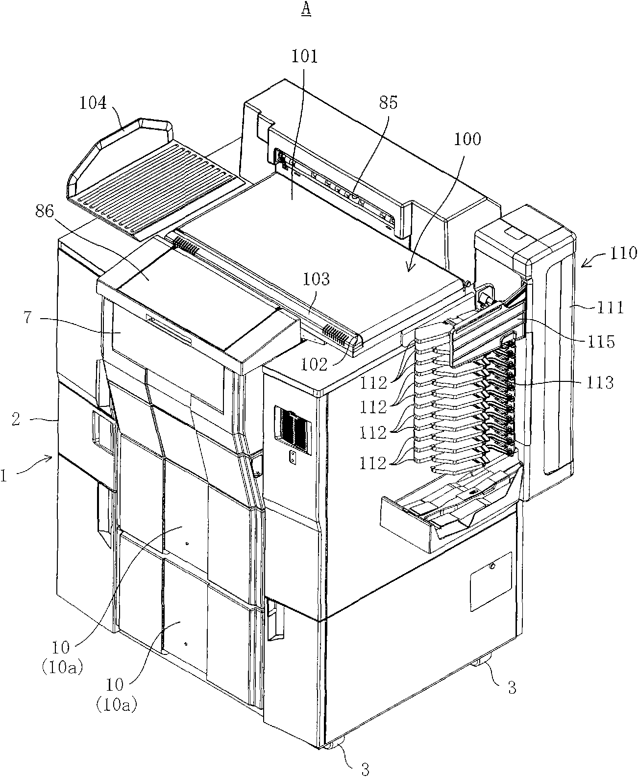
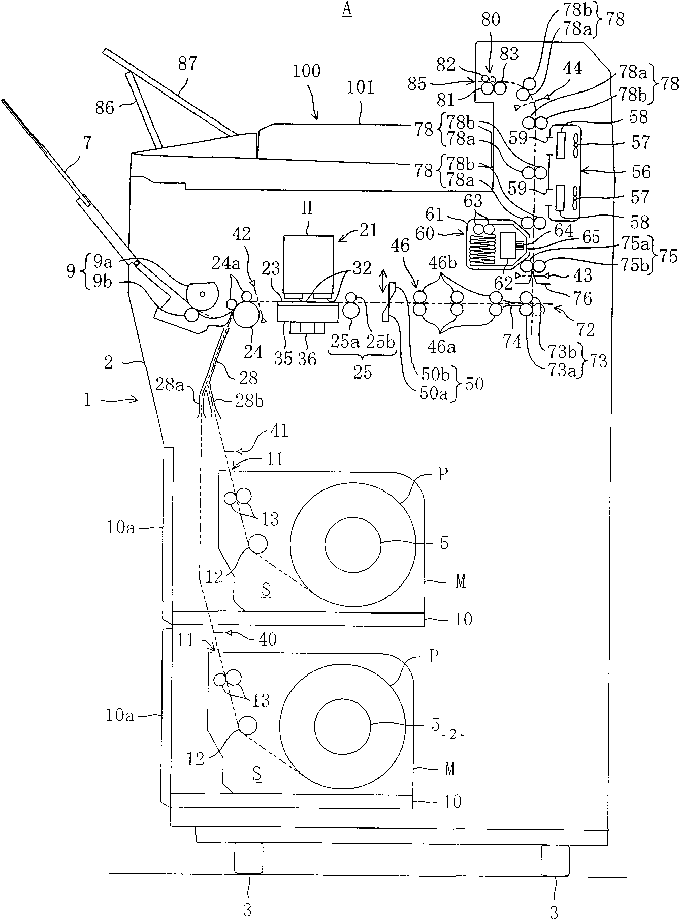
[0023] figure 1 It is a perspective view showing the appearance of an inkjet printer A as an image forming apparatus according to an embodiment of the present invention. figure 2 It is a schematic diagram showing the internal structure of the inkjet printer A seen from the side.

[0024] like figure 1 and figure 2 As shown, the inkjet printer A is used in a photo printing system. For example, the inkjet printer A prints (forms an image) on paper P based on image data transmitted via a communication cable from a receiving module (not shown) that acquires image data and performs necessary correction pr...


PUM


Abstract

The present invention discloses an image forming device allowing a printing section (21) inside of a casing (2) to print paper (P) and discharging the printed paper (P) from the casing (2) through a discharge port (85) of the casing (2), in which a discharge tray (87) is configured such that the position thereof is switchable from a placement position for covering the surface of a feeding belt (101) and receiving the paper (P) discharged from the casing (2) to an exposure position for exposing the surface of the feeding belt (101), and vice versa, wherein a surface of the discharge tray (87) has a coefficient of friction lower than the surface of the feeding belt (101). Thereby, the surface of the feeding belt (101) is prevented from the printing surface of the paper (P), so as to prevent printing quality of the printing surface from decreasing.

Description

technical field [0001] The present invention relates to an image forming apparatus that prints on paper by a printing unit disposed inside the machine, and then discharges the printed paper from a paper discharge port of the machine toward the outside of the machine. Background technique [0002] So far, there have been image forming apparatuses that print on paper using a printing section installed in the body, and then discharge the printed paper from the paper discharge port of the body (upper side of the conveyor belt) (for example, refer to Japanese publication Japanese patent publication No. 2002-23279 communiqué) has been known to the public. The paper caught by the conveyor belt is conveyed by the conveyor belt to the paper gathering device set on the side of the machine, and then the paper gathering device is used to sort according to the specified number of sheets (for example, the number of sheets required by each order). The paper gathering device has a pluralit...

Claims


Application Information

Patent Timeline
Patent Type & Authority Applications(China)
IPC IPC(8): B41J2/01B41J15/18B41J15/04
CPCB65H2408/113B65H2405/1412B65H2801/06B65H2405/324G03G2215/00421B65H31/24G03G15/6573B65H29/18B65H31/02G03G2215/00544B65H39/11B65H2405/1117
Inventor 别当和志南山诚司
Owner NK WORKS CO LTD
Why Eureka
Try Eureka