Paper feeding device

a feeding device and paper technology, applied in the direction of thin material processing, printing, article separation, etc., can solve the problems of increasing production costs, insufficient effectiveness as a means of preventing multiple feedings, and complex structure of the mold for molding the case, etc., to achieve excellent paper feeding performance, low cost, and improve printing quality.

Inactive Publication Date: 2005-06-23
FUNAI ELECTRIC CO LTD
View PDF4 Cites 4 Cited by
  • Summary
  • Abstract
  • Description
  • Claims
  • Application Information

AI Technical Summary

Benefits of technology

[0018] As described above, according to the paper feeding device of this invention, by adding a simple modification to the structure of the paper feeding load applying unit, the magnitude of the paper feeding load will be uniformalized with respect to all the sheets of paper which have been stacked on the paper mount. As the results, the sheets of paper will be fed one by one without causing multiple feed, irrespective of the number of the sheets, and paper jam will not happen. Therefore, it will be possible to provide the paper feeding device having excellent paper feeding performance at a low cost, and further, in case where the paper feeding device has been employed in a printing apparatus or the like, such phenomenon that printing quality may be deteriorated due to occurrence of multiple feed or jam of paper will hardly happen.

Problems solved by technology

However, in this case, the upper face of the case to which the paper feeding load applying unit is mounted must be modified in shape to attain the purpose, and there has been a problem that a structure of a mold for molding the case has become complicated, and a rise of production cost has been inevitable.
Therefore, it is not sufficiently effective as means for preventing the multiple feed, under circumstances where every sheet of paper has a different erection angle, as described referring to FIG. 3.

Method used


Image

  • Paper feeding device
  • Paper feeding device
  • Paper feeding device

Examples


Embodiment Construction

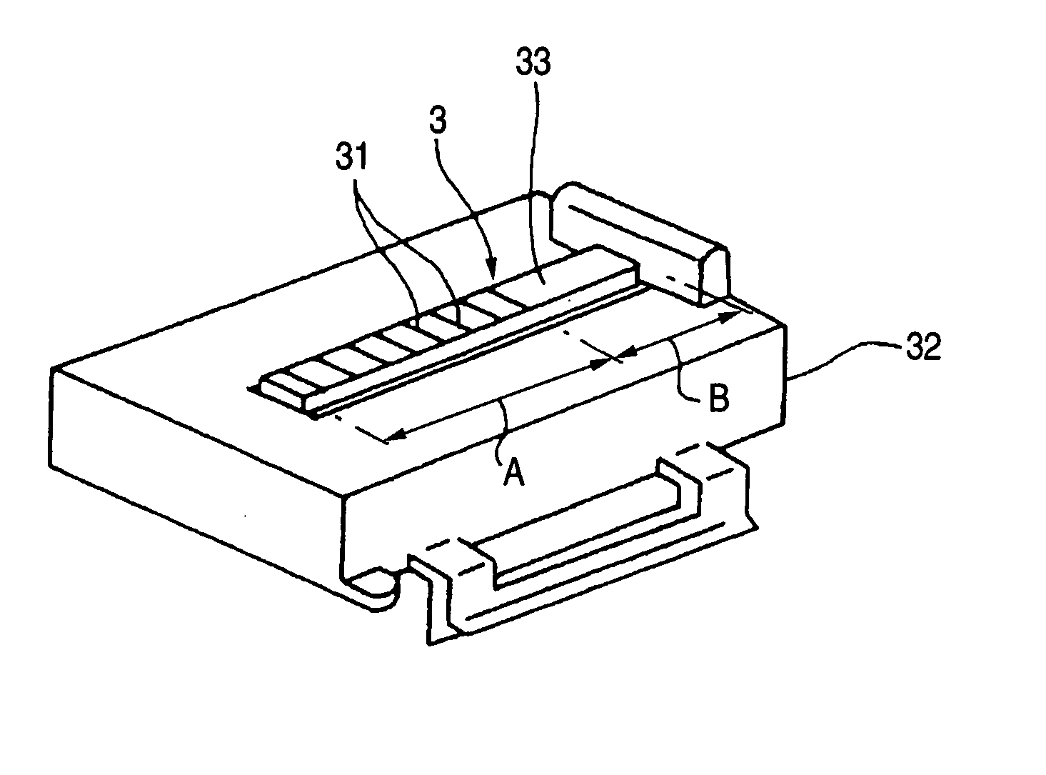
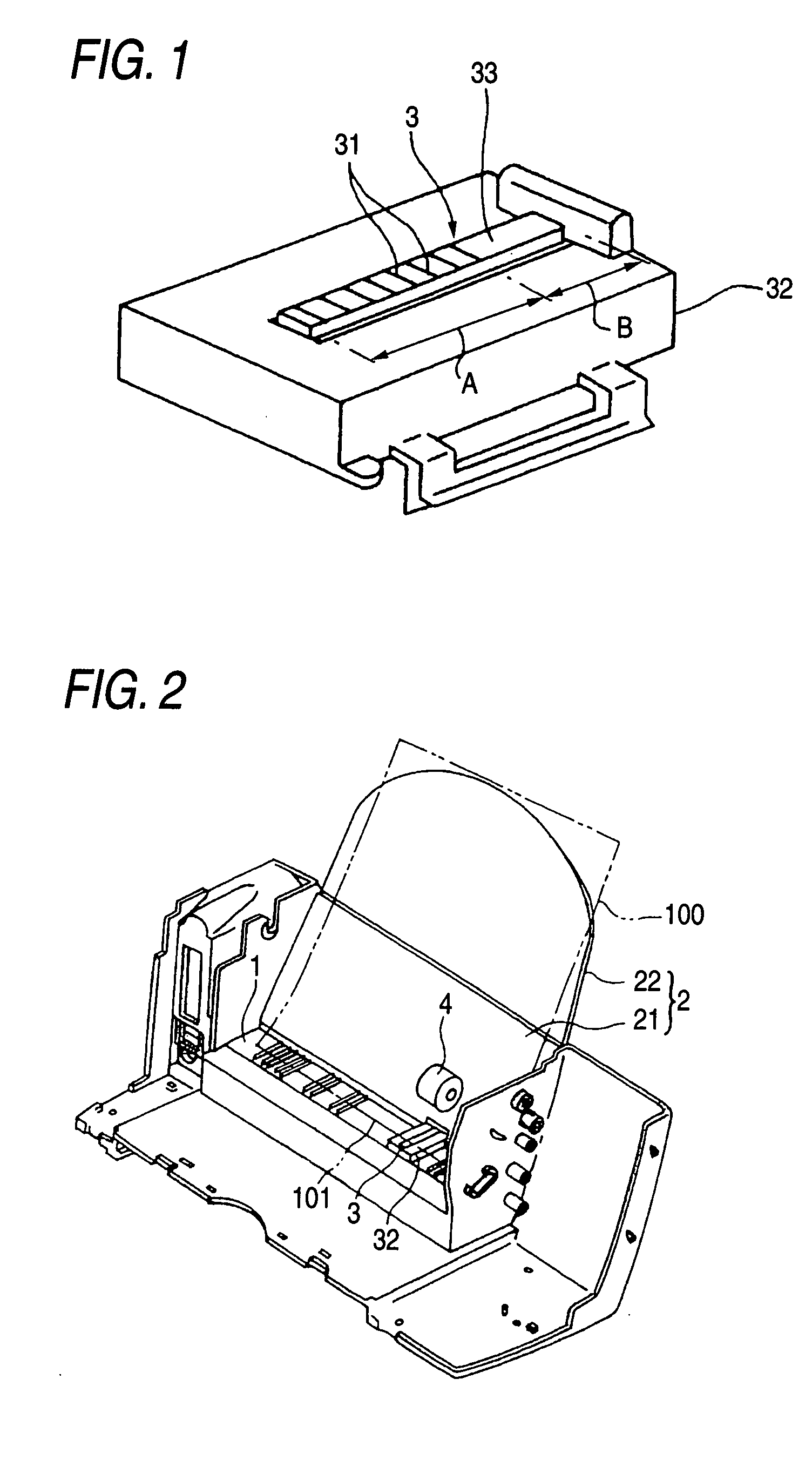
[0025]FIG. 1 is a schematic perspective view showing paper feeding load applying unit 3 employed in a paper feeding device according to the invention, and a case 32 thereof. The feeding load applying unit 3 in the drawing is formed of synthetic resin or rubber into an elongated shape having a surface of rubber material. An area of the surface on which paper edges of a plurality of sheets of paper (not shown) are mounted is divided into a front side region A and a rear side region B in a paper feeding direction. The front side region A in its entirety is provided with convex portions 31 in a serrated shape having a same height which are formed at an equal interval in a longitudinal direction, and the rear side region B is formed as a flat face 33 in its entirety. This feeding load applying unit 3 corresponds to the conventional feeding load applying unit 3 which has been described referring to FIG. 4, in which all the convex portions positioned in a part of the surface corresponding ...


PUM


Abstract

A base part of a paper feeding device for supporting paper edges of a plurality of sheets of paper is provided with paper feeding load applying means which extends in a paper feeding direction and includes a plurality of convex portions having a same height and arranged on a surface of the paper feeding load applying means in parallel in a paper feeding direction, and a paper feeding roller which comes in contact with an uppermost sheet of paper to apply a feeding force to the sheet of paper. A surface of the paper feeding load applying means is divided into a front side region and a back side region, and all the convex portions positioned in the back side region are eliminated thereby to form a flat face in the back side region.

Description

BACKGROUND OF THE INVENTION [0001] 1. Field of the Invention [0002] The present invention relates to a paper feeding device which is employed as a paper feeding mechanism in a printing apparatus such as an inkjet printer, and more particularly, to the paper feeding device which is so designed as to stock paper by mounting a plurality of sheets of paper in a stack on a paper mount erected in a slanted shape. [0003] 2. Description of the Related Art [0004]FIG. 2 is a schematic perspective view for explaining a structure of a paper feeding device of this type. In the drawing, reference numeral 1 designates a base part, 2 designates a paper mount which is divided into a stationary slanted part 21 formed of synthetic resin integrally with the base part 1, and a movable slanted part 22 foldably connected to this stationary slanted part 21. Moreover, a paper feeding load applying unit 3 which is called as “a buckler friction” is provided at one position in a lateral direction of the base p...

Claims


Application Information

Patent Timeline
Patent Type & Authority Applications(United States)
IPC IPC(8): B41J13/00B65H3/52
CPCB65H2405/1114B65H3/56
Inventor MITSUHASHI, MASAAKI
Owner FUNAI ELECTRIC CO LTD
Why Eureka
Try Eureka