
w-band micro coaxial antenna

A coaxial antenna and band technology, applied in the direction of antenna, antenna grounding switch structure connection, electrical components, etc., can solve problems such as restricting the development of high-performance millimeter-wave high-end/terahertz equipment, and achieve improved feeding performance and integration, good Reflection coefficient, effect of shortening length

Active Publication Date: 2022-04-19
湖南国科雷电子科技有限公司
View PDF0 Cites 0 Cited by
  • Summary
  • Abstract
  • Description
  • Claims
  • Application Information

AI Technical Summary

Problems solved by technology

At present, the integration technology based on traditional planar hybrid circuits or machining waveguides has insurmountable defects in volume, integration, loss, etc., which seriously restricts the development of high-performance millimeter-wave high-end / terahertz equipment.

Method used


Image

  • w-band micro coaxial antenna
  • w-band micro coaxial antenna
  • w-band micro coaxial antenna

Examples


Embodiment Construction

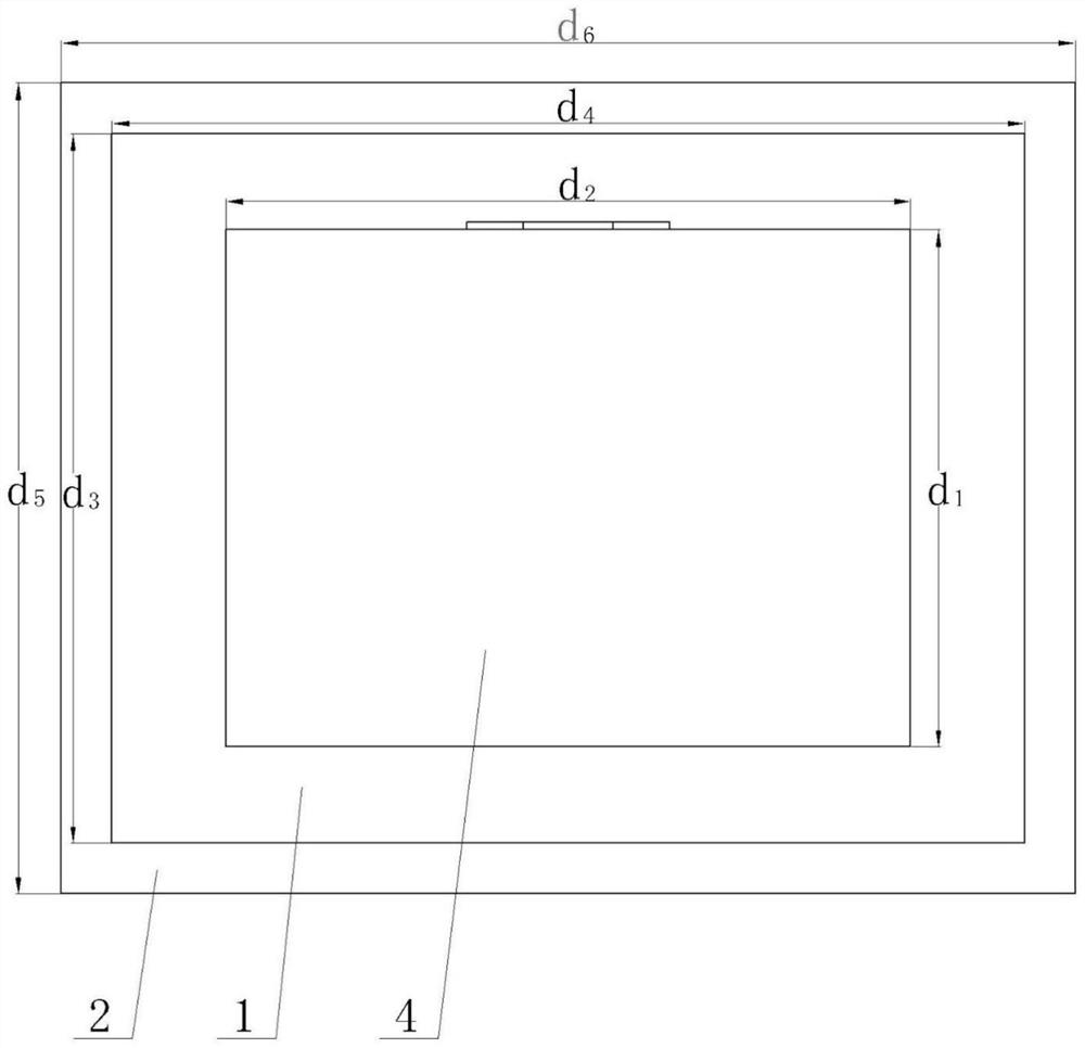
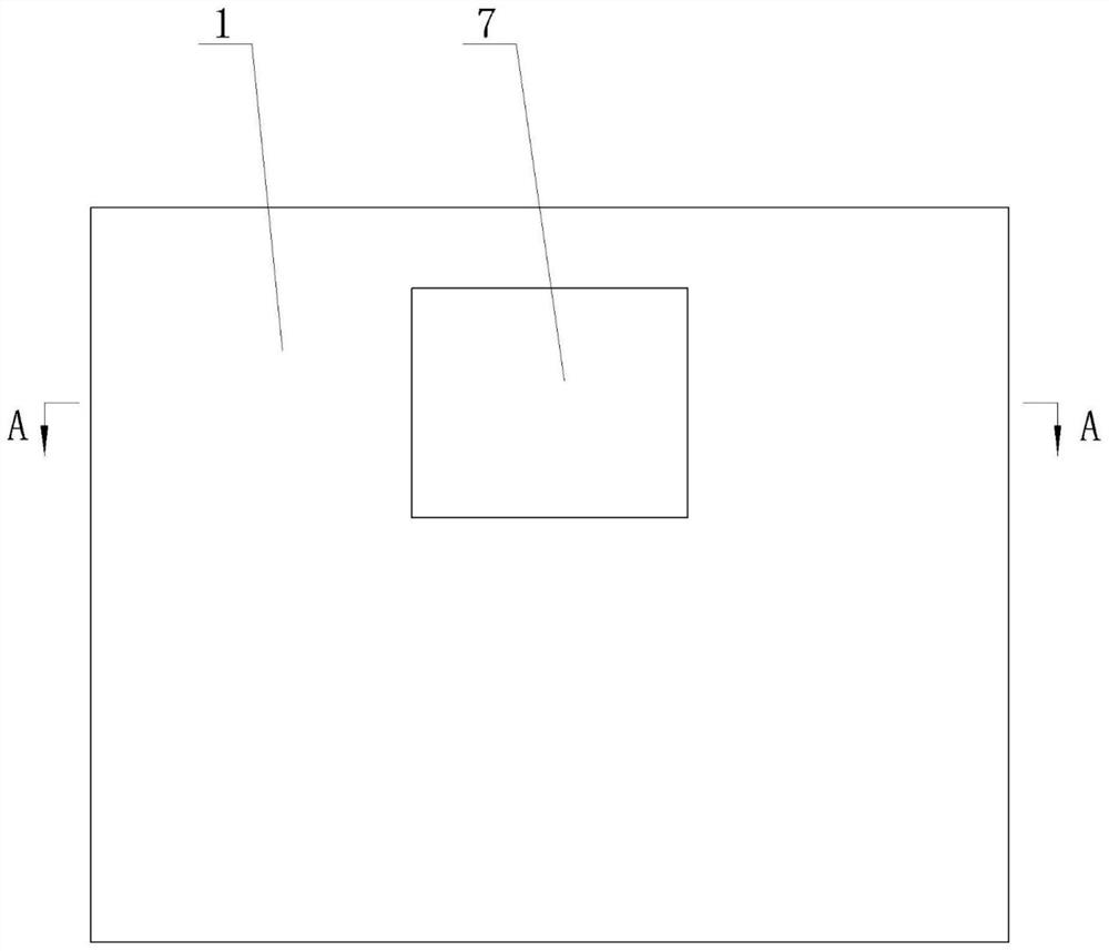
[0032] as attached Figure 1-5 As shown, the W-band micro-coaxial antenna includes a backplane 1, an electric wall 2 is arranged vertically around the backplane 1, one end of a column 3 is arranged on one side of the backplane 1, and a radiation plate 4 is arranged at the other end of the column 3, and a radiation plate 4 is arranged on the radiation plate 4. One end of the fixed rod 5 is provided, and a fixed hole 6 is provided through the back plate 1. The other side of the back plate 1 is provided with a fixed cover 7, one side of the fixed cover 7 is opened, and a window is arranged on the other side of the fixed cover 7. The fixed rod 5 The other end extends out of the fixing hole 6 and is located in the fixing cover 7, and the end face of the other end faces the window opening of the fixing cover 7, so that the fixing rod 5 and the fixing cover 7 are coaxial, and the fixing cover 7 and the fixing rod 5 form a feeder. electrical port. Air exists between the radiation pla...


PUM


Abstract

The invention relates to the field of antennas, in particular to a W-band micro-coaxial antenna, which includes a backboard, an electric wall is arranged vertically around the backboard, one end of a column is arranged on one side of the backboard, a radiation plate is arranged at the other end of the column, and a fixed One end of the rod is provided with a fixing hole through the back plate, the other side of the back plate is provided with a fixed cover, one side of the fixed cover is open, a window is arranged on the fixed cover, and the other end of the fixed rod extends out of the fixed hole and is located in the fixed cover. The other end face of the fixing rod faces the opening of the fixing cover. The working frequency of the present invention is in the W band. In this frequency band, the relative bandwidth is relatively small and the working wavelength is very short. Therefore, the volume and weight of devices and systems are greatly reduced, and the transmission path length can be shortened to a certain extent. The millimeter wave can be transmitted with ultra-low loss on the feed port composed of the fixed cover and the fixed rod, and the feed port has a good reflection coefficient, which plays an effective role in improving the feed performance and integration.

Description

technical field [0001] The invention relates to the field of antennas, in particular to a W-band micro-coaxial antenna. Background technique [0002] The level of informatization of equipment directly determines the balance of power between the parties in the war. Thanks to the characteristics of high resolution, strong orientation, and large bandwidth, the millimeter wave high-end / terahertz electronic system has very broad application prospects in the fields of large-capacity communication, high-performance radar, and high-precision guidance. At present, integration technologies based on traditional planar hybrid circuits or machined waveguides have insurmountable defects in volume, integration, loss, etc., which seriously restrict the development of high-performance millimeter-wave high-end / terahertz equipment. Contents of the invention [0003] The technical problem to be solved by the present invention is that millimeter-wave / terahertz devices are bulky. In order to s...

Claims


Application Information

Patent Timeline
Patent Type & Authority Patents(China)
IPC IPC(8): H01Q1/36H01Q1/50H01Q15/14
CPCH01Q1/36H01Q1/50H01Q15/14
Inventor 刘博源张德平袁文韬叶源陈嘉贝黄昭宇江云季鹏飞
Owner 湖南国科雷电子科技有限公司
Learn More