Printer apparatus

Inactive Publication Date: 2005-09-29
CANON KK
View PDF7 Cites 5 Cited by
  • Summary
  • Abstract
  • Description
  • Claims
  • Application Information

AI Technical Summary

Benefits of technology

[0018] Thus, the endless belt is conveyed by driving not the platen roller but another roller, so that the printing conditions in the platen roller portion are compatible with the conditions that the endless belt is conveyed with high accuracy. In the thermal recording printer apparatus having the configuration in which the printing is performed with the small-diameter platen roller having the advantages for the miniaturization and the reduction in thickness of the apparatus, the endless belt can be conveyed with high accuracy to perform the

Problems solved by technology

Further, a mechanism (not shown) which holds the recording sheet while the recording sheet is wound around the platen roller is also required, so that the first example has a demerit that the apparatus becomes complicated.
However, in the configuration disclosed in Japanese Patent Application Laid-Open No. 2003-39760, the mechanism which winds the recording sheet around the platen roller is further complicated.
Accordingly, the problems of the upsizing and the complication, which the conventional first example potentially owns, become further pronounced.
However, because hardness and a nip width of the platen roller are set so as to satisfy printing conditions caused by pressures and contact statuses between the thermal head and the ink sheet and between the ink sheet and the recording sheet, it is difficult to set the hardness and the nip width of the platen roller to the same level as for the capstan roller which has recording-sheet conveying accuracy necessary for the full color printing.
On the contrary, when the hardness and the nip width of the platen roller are set to the same level as for the capstan roller which has the recording-sheet conveying accuracy necessary for the full color printing, there is a considerably high

Method used


Image

  • Printer apparatus
  • Printer apparatus
  • Printer apparatus

Examples


first embodiment

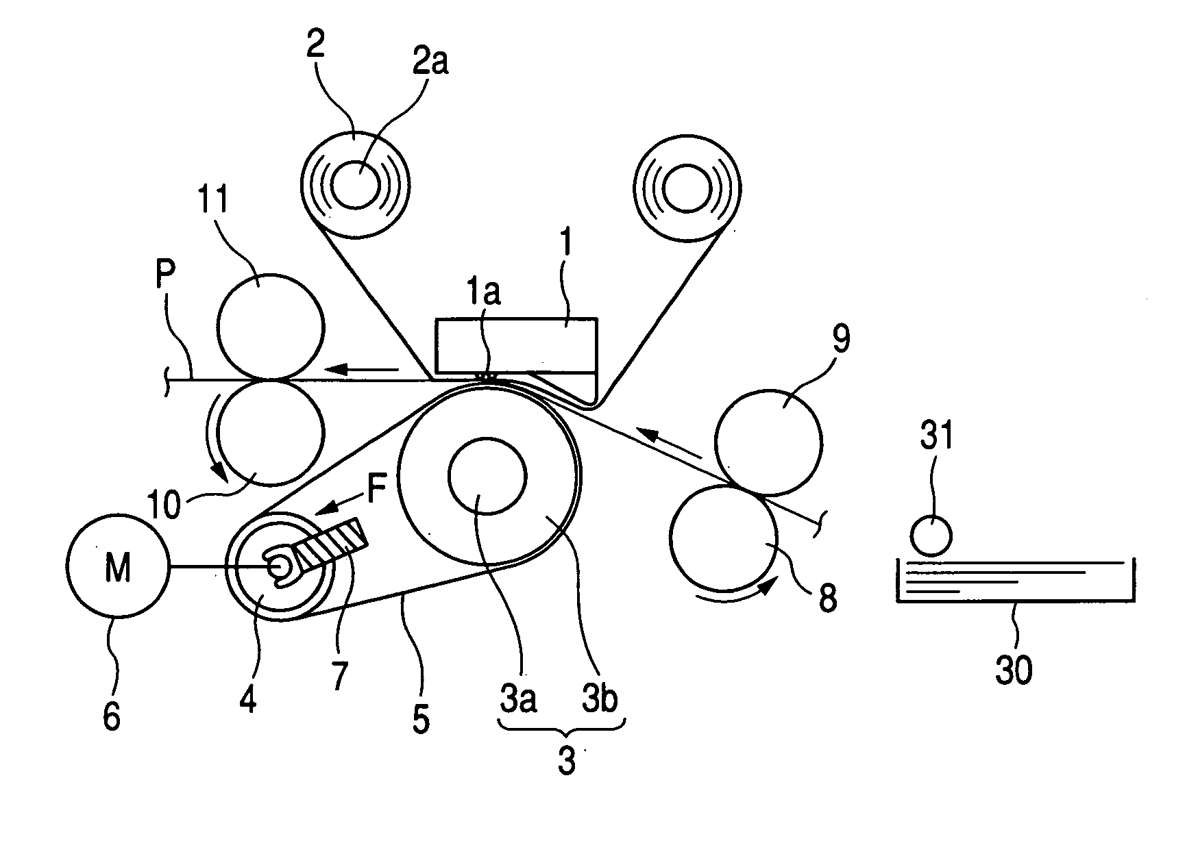
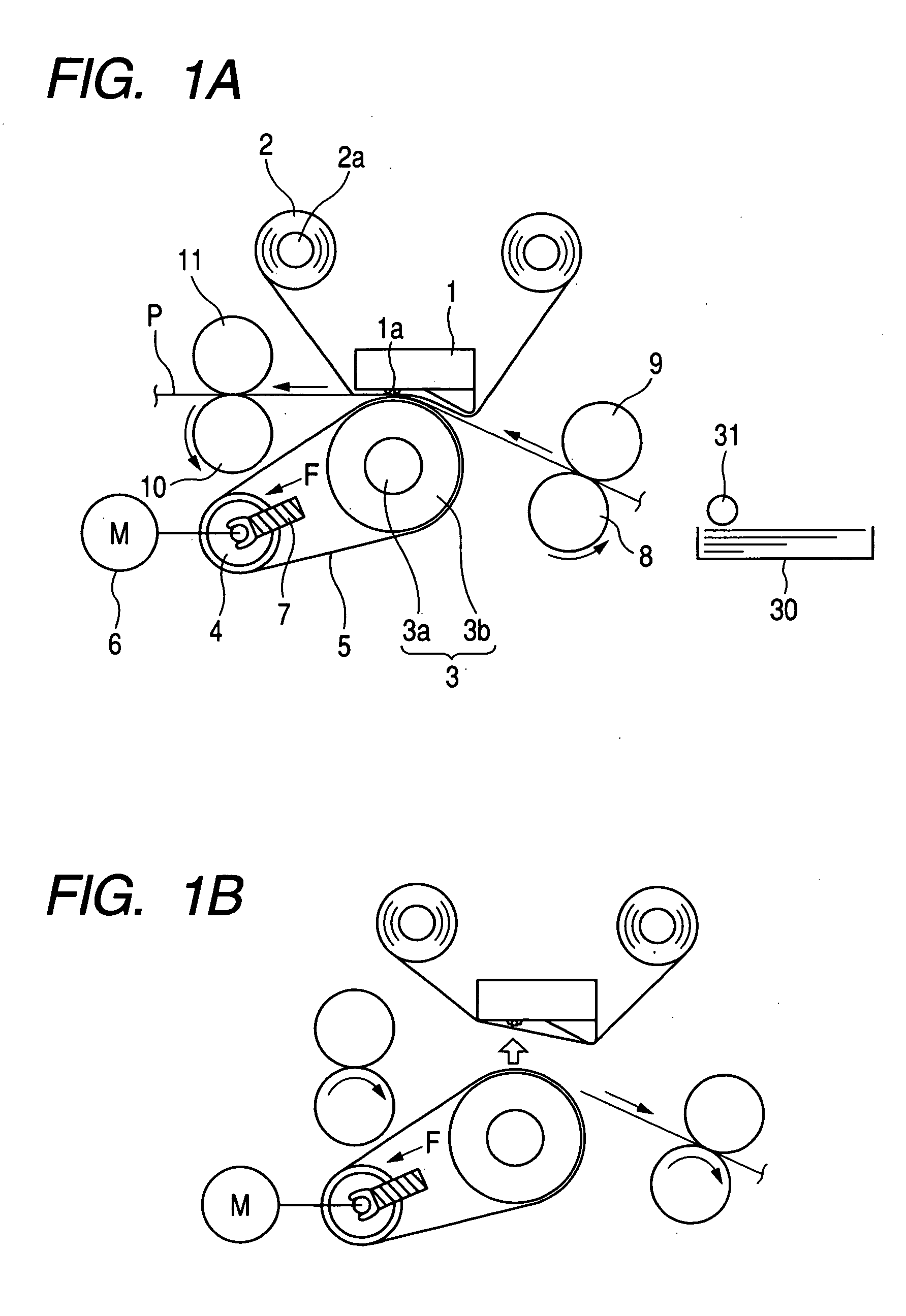
[0030]FIGS. 1A and 1B show a thermal recording printer apparatus or an image forming apparatus according to a first embodiment of the invention.

[0031] In FIG. 1A, the reference numeral 1 denotes a thermal head in which a heat generating unit 1a is formed. In the heat generating unit 1a, plural heating elements or plural heating resistors are linearly arranged. The reference numeral 2 denotes an ink sheet to which ink is applied. The reference numeral 3 denotes a platen roller which is of a pressing member or a guide member. The platen roller 3 is provided opposite to the heat generating unit of the thermal head 1 while being parallel to the heat generating unit. The platen roller 3 includes a central axis 3a and an elastic rubber roller 3b. The reference numeral 4 denotes a drive roller which is of a first roller provided in parallel with the platen roller 3. The reference numeral 5 denotes an endless belt which is extended or extended with a tension so as to involve the platen rol...

second embodiment

[0057]FIGS. 5A and 5B show thermal recording printer apparatus according to a second embodiment of the invention. In FIGS. 5A and 5B, the reference numeral 1 denotes the thermal head in which the heat generating unit 1a is formed. In the heat generating unit 1a, the plural heating resistors are linearly arranged. The reference numeral 2 denotes the ink sheet to which the ink is applied. The reference numeral 3 denotes the platen roller which is of the pressing member. The platen roller 3 is provided opposite to the heat generating unit of the thermal head 1 while being parallel to the heat generating unit. The platen roller 3 includes the central axis 3a and the elastic rubber roller 3b. The reference numeral 4 denotes the drive roller which is provided in parallel with the platen roller 3. The reference numeral 21 denotes an auxiliary roller which is of a second roller provided in parallel with the platen roller 3. The auxiliary roller 21 is rotatably supported. The reference numer...

third embodiment

[0065]FIGS. 6A and 6B show a thermal transfer type printer apparatus according to a third embodiment of the invention. In FIGS. 6A and 6B, the reference numeral 1 denotes the thermal head in which the heat generating unit 1a is formed. In the heat generating unit 1a, the plural heating resistors are linearly arranged. The reference numeral 2 denotes the ink sheet to which the ink is applied. The reference numeral 3 denotes the platen roller which is of the pressing member. The platen roller 3 is provided opposite to the heat generating unit of the thermal head 1 while being parallel to the heat generating unit. The platen roller 3 includes the central axis 3a and the elastic rubber roller 3b. The reference numeral 4 denotes the drive roller which is provided in parallel with the platen roller 3. The reference numeral 21 denotes the auxiliary roller which is provided in parallel with the platen roller 3. The reference numeral 5 denotes the endless belt which is extended with a tensio...


PUM


Abstract

An object of the invention is to provide a printer apparatus which can perform printing to the whole surface of a recording sheet with no margin while print quality is not lost. A configuration of the invention is a printer apparatus which has a printing unit comprising a pressing member which is provided in parallel with a heat generating unit of the thermal head while being opposite the heat generating unit of the thermal head; a first roller which is provided in parallel with the pressing member; and an endless belt which is extended with a tension so as to involve the pressing member and the first roller. In the printer apparatus, the thermal head is pressed against the pressing member through an ink sheet and the endless belt, the recording sheet is conveyed between the ink sheet and the endless belt, and the printing is performed by transferring ink in the ink sheet to the recording sheet with the thermal head.

Description

BACKGROUND OF THE INVENTION [0001] 1. Field of the Invention [0002] The present invention relates to a printer apparatus which prints an image in a recording material such as a recording sheet based on image information. [0003] 2. Related Background Art [0004] Conventionally, printer apparatuses which are used for an output device of a computer or the output device for digital images can be divided into a thermal transfer type printer apparatus, an ink jet printer apparatus, a laser printer apparatus, a dot-wire printer apparatus and the like according to the recording methods. In the conventional printer apparatuses, line thermal transfer type printer apparatus is one in which an ink sheet and the recording sheet are used, plural heat generating elements arrayed in a main scanning direction are selectively driven while the ink sheet and the recording sheet are conveyed in a sub-scanning direction, and thereby the dot line-shaped image printing can be performed onto the recording sh...

Claims


Application Information

Patent Timeline
IPC IPC(8): B41J2/325B41J11/00B41J11/04
CPCB41J2/325B41J11/04B41J11/007
Inventor NISHITANI, HITOSHI
Owner CANON KK
Why Eureka
Try Eureka