High-resolution printing device and printing equipment

A printing device and high-resolution technology, applied in the field of print heads, can solve the problems of difficulty in improving resolution, high cost, and high price of print heads

Pending Publication Date: 2020-03-06
KOCEL INTELLIGENT FOUNDRY IND INNOVATION CENT CO LTD
View PDF0 Cites 5 Cited by
  • Summary
  • Abstract
  • Description
  • Claims
  • Application Information

AI Technical Summary

Problems solved by technology

[0002] At present, the resolution of the print head nozzle of the 3D printing equipment affects the accuracy and quality of the subsequent products. The higher the resolution, the finer the product text

Method used


Image

  • High-resolution printing device and printing equipment
  • High-resolution printing device and printing equipment
  • High-resolution printing device and printing equipment

Examples


Embodiment 1

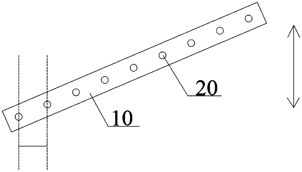
[0064] Refer to attached figure 2 As shown, a high-resolution printing device performs inkjet work along the printing direction, including a nozzle 10 and an installation base 30, and at least one row of uniform nozzle holes 20 is arranged on the nozzle 10, and the nozzle 10 is arranged on the On the above-mentioned installation base 30, the angle between the straight line where the row of nozzle holes 20 is located and the straight line where the printing direction is located in the same horizontal plane is not equal to 90°, and the straight line where the row of nozzle holes 20 is located and the direction where the printing direction is located in the same horizontal plane are not equal to 90°. The angle formed by the straight line is not equal to 0°.

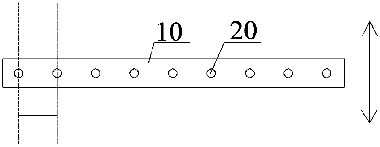
[0065] It can be seen that using this scheme, using and attaching figure 1 The spray head 10 of the same resolution, but inclined to reduce the distance between the nozzle holes 20 and the nozzle holes 20, thereby achievin...

Embodiment 2

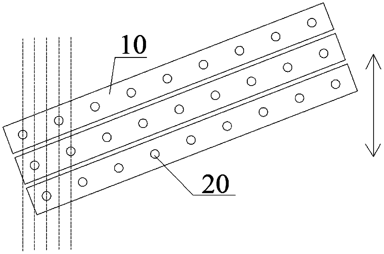
[0067] Refer to attached image 3 As shown, a high-resolution printing device performs inkjet work along the printing direction, including a nozzle 10 and an installation base 30, the nozzle 10 is arranged on the installation base 30, and the nozzle 10 is arranged in two or two rows Above the nozzle holes 20, the straight line where one row of nozzle holes 20 is located is parallel to the straight line where another row of nozzle holes 20 is located, and all the nozzle holes 20 are in an array, wherein the straight line where the horizontal row of nozzle holes 20 is located is perpendicular to the straight line where the column row of nozzle holes 20 is located. The included angle formed by the straight line where the row of nozzle holes 20 is located and the straight line where the printing direction is located in the same horizontal plane is not equal to 90°, and the included angle formed by the straight line where the row of nozzle holes 20 is located and the straight line w...

Embodiment 3

[0071] Refer to attached Figure 4As shown, a high-resolution printing device performs inkjet work along the printing direction, including a nozzle 10 and an installation base 30, the nozzle 10 is arranged on the installation base 30, and the nozzle 10 is arranged in two or two rows Above the nozzle holes 20, the straight line where one row of nozzle holes 20 is located is parallel to the straight line where the other row of nozzle holes 20 is located, and all the nozzle holes 20 are in an array, wherein the straight line where the horizontal row of nozzle holes 20 is located and the straight line where the column row of nozzle holes 20 are located are formed The included angle is not equal to 90°. The included angle formed by the straight line where the row of nozzle holes 20 is located and the straight line where the printing direction is located in the same horizontal plane is not equal to 90°, and the included angle formed by the straight line where the row of nozzle holes...


PUM


Abstract

The invention disclose a high-resolution printing device and printing equipment. The high-resolution printing device carries out ink jetting operation in the printing direction and comprises a sprayerand a mounting base, wherein at least one row of uniform jetting orifices is formed in the sprayer; the sprayer is arranged on the mounting base; and the included angle formed by the straight line ofthe row of jetting orifices and the straight line of the printing direction within the same plane is not equal to 90 degrees and also is not equal to 0 degree. On the basis of the sprayer with the existing resolution, the resolution is increased through changing the arrangement form, so that the resolution is increased without increasing the cost to realize a high resolution effect; and if the resolution is increased, the bonding power among the particle material is also increased to further improve the product quality.

Description

technical field [0001] The present invention relates to the field of printing heads related to additive manufacturing 3D printing equipment, in particular to a high-resolution printing device and printing equipment. Background technique [0002] At present, the resolution of the print head nozzle of the 3D printing equipment affects the accuracy and quality of the subsequent products. The higher the resolution, the finer the product texture, and the strength will be improved, but it is still difficult to improve the resolution. The latest high-resolution The price of the high-rate print head is extremely high, making the cost too high. Contents of the invention [0003] Aiming at the deficiencies of the prior art, the present invention provides a high-resolution printing device and printing equipment. A technical problem solved by one aspect of the present invention is to improve the resolution of the nozzles of the print head without increasing the cost on the existing ba...

Claims


Application Information

Patent Timeline
IPC IPC(8): B29C64/165B29C64/205B29C64/209B29C64/35B29C64/321B33Y30/00B33Y40/00
CPCB29C64/165B29C64/205B29C64/209B29C64/321B29C64/35B33Y30/00B33Y40/00
Inventor 王军伟马玺孙旺刘轶
Owner KOCEL INTELLIGENT FOUNDRY IND INNOVATION CENT CO LTD
Why Eureka
Try Eureka