Exhaust apparatus for transverse engine

一种排气装置、排气净化装置的技术,应用在排气装置、动力装置、发动机元件等方向,能够解决温度不会及早上升、隧道部截面积增大、增大等问题

Inactive Publication Date: 2011-06-08
MAZDA MOTOR CORP
View PDF7 Cites 2 Cited by
  • Summary
  • Abstract
  • Description
  • Claims
  • Application Information

AI Technical Summary

Problems solved by technology

[0005] However, if the two intermediate converging pipe parts are arranged in the above-mentioned tunnel part in this way, the width, height (cross-sectional area), etc. of the tunnel part will increase. At the confluence pipe part, the cross-sectional area of ​​the tunnel part will be further increased
Therefore, there is still room for improvement from the viewpoint of securing the vehicle interior space as wide as possible.
In addition, if the exhaust purification device is installed in the tunnel part, the vehicle running wind will easily blow to the exhaust purification device, so the temperature of the catalyst in the exhaust purification device will not rise early when the engine is low temperature. From this point of view, There is also room for improvement

Method used


Image

  • Exhaust apparatus for transverse engine
  • Exhaust apparatus for transverse engine
  • Exhaust apparatus for transverse engine

Examples


Embodiment approach 1

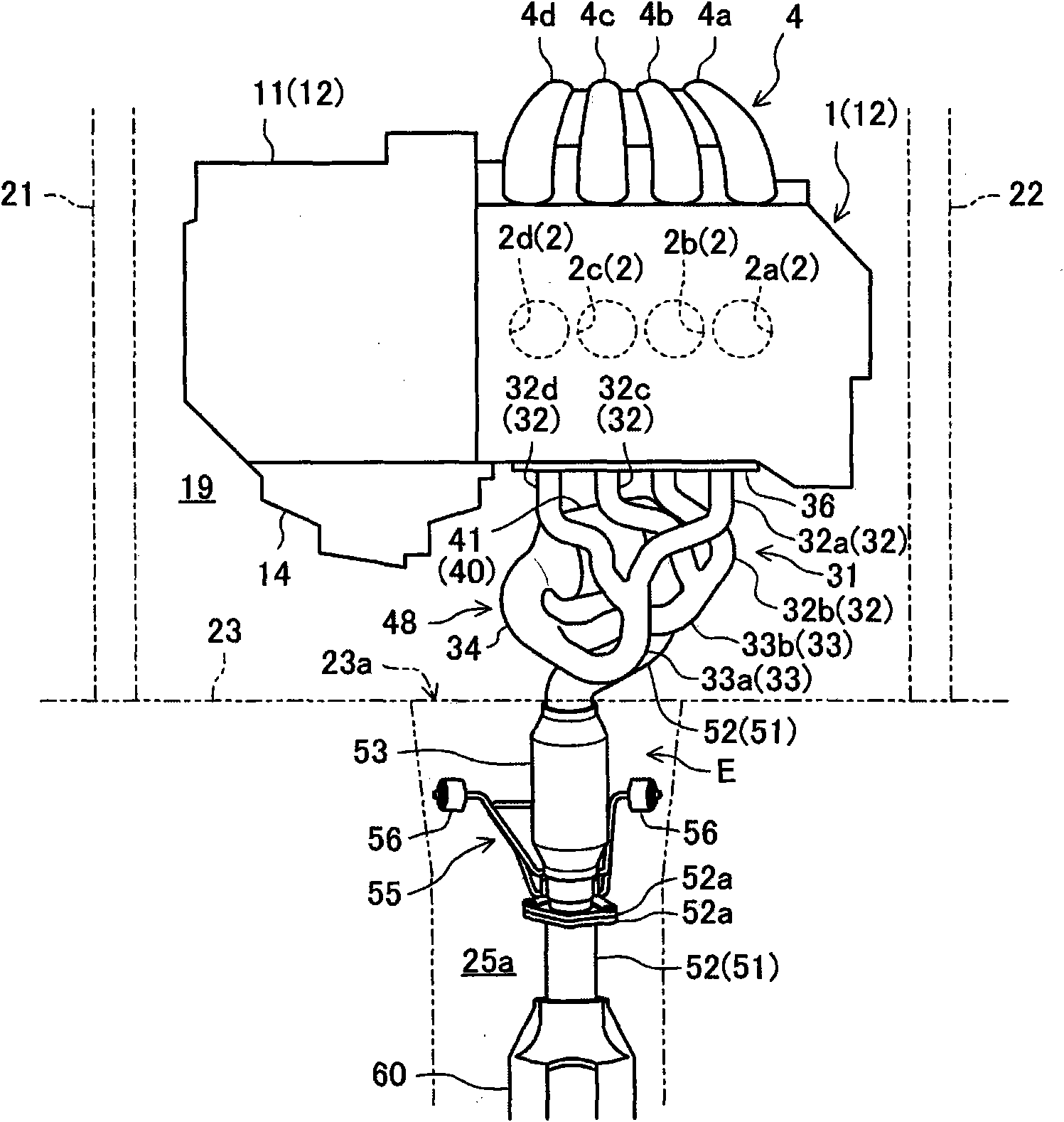
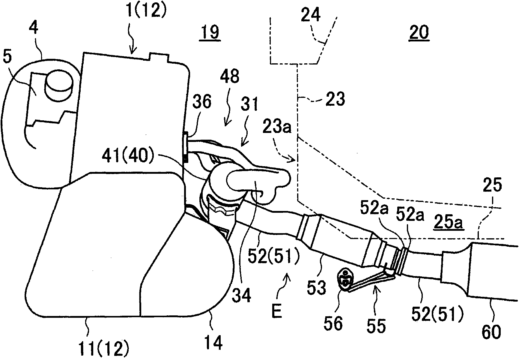
[0022] figure 1 and figure 2 An exhaust device E according to Embodiment 1 of the present invention is shown, and this exhaust device E is an exhaust device of the transverse engine 1 . This engine 1 is an in-line 4-cylinder engine having four cylinders 2 in a row, and it faces the vehicle width direction ( figure 1 The engine room 19 of the front part of the vehicle is arranged laterally in the state of the left-right direction of the vehicle. Below, will correspond to figure 1 to the right of ( figure 2 The right side of the vehicle on the back side of the paper) is called the right side of the vehicle and will correspond to figure 1 to the left of ( figure 2 The left side of the vehicle) is called the left side of the vehicle and will correspond to figure 1 the upper side of ( figure 2 The front side of the vehicle on the left side) is called the vehicle front side and will correspond to figure 1 the lower side of ( figure 2 The rear side of the vehicle is cal...

Embodiment approach 2

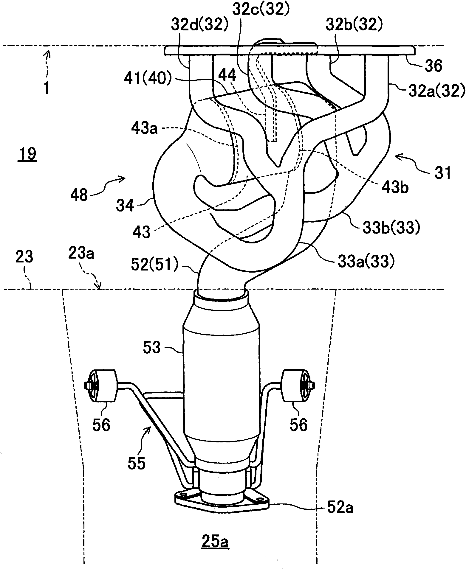
[0055] Figure 6 ~ Figure 8 Showing Embodiment 2 of the present invention, the end portions on the exhaust upstream side of the first and second intermediate converging pipe portions 33a and 33b (the converging portion of the first branch pipe portion 32a and the fourth branch pipe portion 32d, and the second branch pipe portion The positional relationship between the pipe portion 32b and the confluence portion of the third branch pipe portion 32c is different from that of Embodiment 1 described above.

[0056] That is, in the present embodiment, the ends on the exhaust gas upstream side of the first and second intermediate converging pipe portions 33a, 33b are arranged at approximately the same position as the third joining portion 37c in the vehicle width direction, and are arranged in the vertical direction. misplaced configurations. Specifically, the method of merging the first branch pipe part 32a and the fourth branch pipe part 32d is the same as that of the first embod...

Embodiment approach 3

[0062] Figure 9 ~ Figure 11 Showing Embodiment 3 of the present invention, the end portions on the exhaust gas upstream side of the first and second intermediate converging pipe portions 33a, 33b (the converging portion of the first branch pipe portion 32a and the fourth branch pipe portion 32d, and the second branch pipe portion The positional relationship between the pipe portion 32b and the confluence portion of the third branch pipe portion 32c is further different.

[0063]That is, in the present embodiment, the exhaust gas upstream end portions of the first and second intermediate converging pipe portions 33a, 33b are arranged at approximately the same position as the third joint portion 37c in the vehicle width direction, as in the second embodiment described above. However, the exhaust gas upstream end portions of the first and second intermediate converging pipe portions 33a, 33b do not overlap each other in plan view, and are displaced from each other in the vehicle...


PUM


Abstract

The present invention provides an exhaust apparatus for a transverse engine. An exhaust upstream section (48) of the exhaust apparatus (E) comprises a plurality of branch pipe portions (32), a plurality of intermediate collector pipe portions (33), a final collector pipe portion (34), and an exhaust gas-purifying unit (40). The exhaust gas-purifying unit (40) is disposed on a vehicle-rear side of an engine (1) to allow a gas passage thereinside to extend approximately in a vehicle-widthwise direction, in top plan view. Each of the plurality of intermediate collector pipe portions (33) curves to allow an exhaust downstream region of the intermediate collector pipe portion (33) to be oriented toward one side or the other side of the vehicle-widthwise direction, in top plan view, and the final collector pipe portion (34) curves to allow an exhaust downstream region of the final collector pipe portion (34) to be oriented toward a vehicle-front side, in top plan view. This makes it possible to compactly lay out the exhaust upstream section (48) in an engine compartment (19) without sacrificing a passenger compartment space, and quickly raise a temperature of a catalyst in an exhaust gas-purifying unit (40) during warm-up of the engine (1).

Description

technical field [0001] The present invention relates to an exhaust device for a transversely mounted engine disposed transversely in an engine room at the front of a vehicle with the cylinder row direction facing the vehicle width direction. Background technique [0002] Conventionally, such a transverse engine is well known, and the exhaust device of the transverse engine is generally arranged on the vehicle rear side of the engine (for example, refer to Japanese Patent Laid-Open Publication No. 2008-260472 (Patent Document 1)). The exhaust device has a plurality of branch pipes respectively communicating with a plurality of cylinders of the engine, and these branch pipes merge to finally form a merged pipe. In this device of Patent Document 1, all the cylinders (four cylinders) are divided into groups of cylinder groups (the cylinder group consisting of the first cylinder and the fourth cylinder, and Cylinder group consisting of the second cylinder and the third cylinder)...

Claims


Application Information

Patent Timeline
Patent Type & Authority Applications(China)
IPC IPC(8): B60K13/04F01N3/10F01N13/08
CPCF01N13/1816F01N2340/04F01N3/10F01N13/08F01N13/10F01N13/1822Y02A50/20
Inventor 牛岛贤儿长谷川裕一中谷泰史北畠启史楠泰史加茂寿章中村好孝渡边大辅下地博喜根上昌巳
Owner MAZDA MOTOR CORP
Why Eureka
Try Eureka