Exhaust apparatus for transverse engine

A technology for exhaust devices and exhaust purification devices, which is applied in the direction of exhaust devices, power devices, engine components, etc., and can solve problems such as the temperature will not rise early, the cross-sectional area of ​​​​the tunnel will increase, and the increase

Inactive Publication Date: 2011-06-08
MAZDA MOTOR CORP
View PDF1 Cites 5 Cited by
  • Summary
  • Abstract
  • Description
  • Claims
  • Application Information

AI Technical Summary

Problems solved by technology

[0005] However, if the two intermediate converging pipe parts are arranged in the above-mentioned tunnel part in this way, the width, height (cross-sectional area), etc. of the tunnel part will increase. At the confluence pipe part, the cross-sectional area of ​​the tunnel part will be further increased
Therefore, there is still room for improvement from the viewpoint of securing the vehicle interior space as wide as possible.
In addition, if the exhaust purification device is installed in the tunnel part, the vehicle running wind will easily blow to the exhaust purification device, so the temperature of the catalyst in the exhaust purification device will not rise early when the engine is low temperature. From this point of view, There is also room for improvement

Method used


Image

  • Exhaust apparatus for transverse engine
  • Exhaust apparatus for transverse engine
  • Exhaust apparatus for transverse engine

Examples


Embodiment approach 1

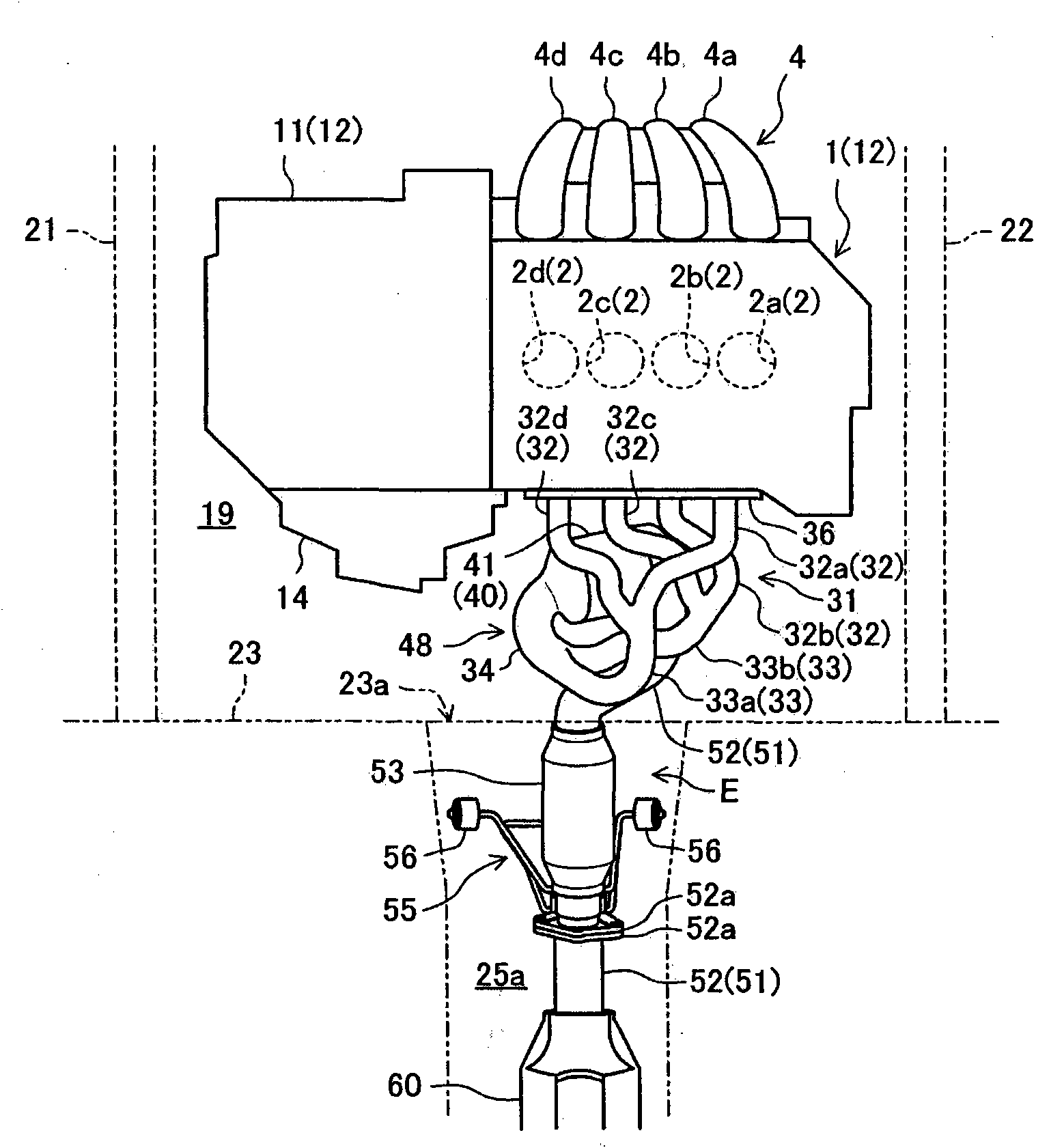
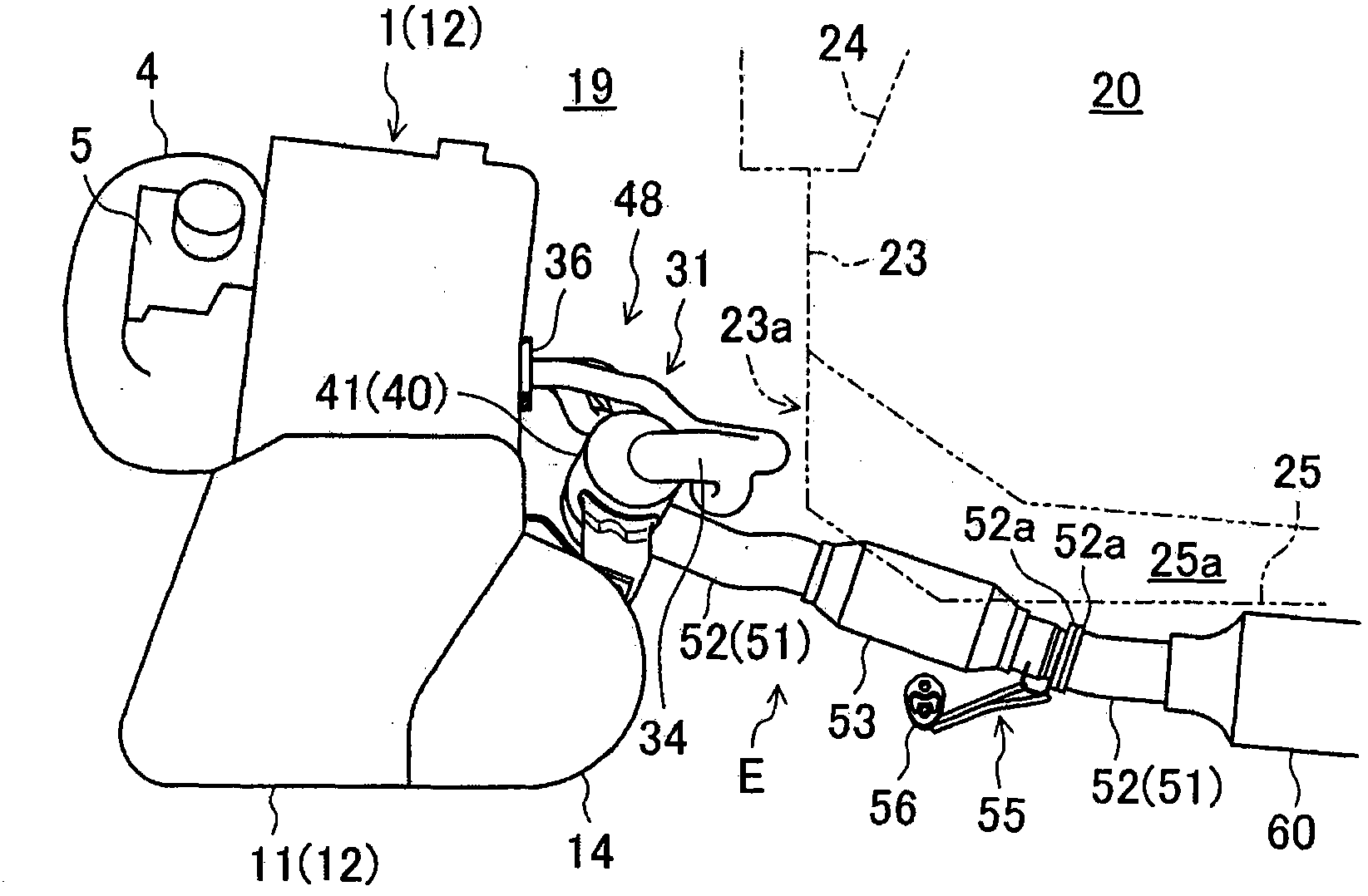
[0025] figure 1 and figure 2 The exhaust device E according to the first embodiment of the present invention is shown, and the exhaust device E is an exhaust device of the engine 1 placed horizontally. The engine 1 is an in-line 4-cylinder engine having four cylinders 2 in a row, and the row direction of the cylinder faces the vehicle width direction ( figure 1 The state of the left-right direction) is laterally arranged in the engine room 19 at the front of the vehicle. Below, will correspond to figure 1 The right side of ( figure 2 The right side of the vehicle is called the right side of the vehicle and will correspond to figure 1 Left of ( figure 2 The left side of the vehicle is called the left side of the vehicle and will correspond to figure 1 The upper side ( figure 2 The front side of the vehicle is called the front side of the vehicle and will correspond to figure 1 The underside ( figure 2 The rear side of the vehicle is called the rear side of the vehicle.

[0026...

Embodiment approach 2

[0058] Figure 6 ~ Figure 8 Shows the second embodiment of the present invention, the ends of the first and second intermediate merging pipe portions 33a, 33b on the exhaust upstream side (the merging portion of the first branch pipe portion 32a and the fourth branch pipe portion 32d, and the second branch The positional relationship between the pipe portion 32b and the junction of the third branch pipe portion 32c) is different from that of the first embodiment described above.

[0059] That is, in the present embodiment, the end portions on the exhaust upstream side of the first and second intermediate junction pipe portions 33a, 33b are both arranged in the vehicle width direction at substantially the same position as the third junction portion 37c, and are arranged in the vertical direction. Misplaced configuration. Specifically, the method of joining the first branch pipe portion 32a and the fourth branch pipe portion 32d is the same as that of the above-mentioned first embo...

Embodiment approach 3

[0065] Figure 9~Figure 11 In the third embodiment of the present invention, the ends on the exhaust upstream side of the first and second intermediate merging pipe portions 33a, 33b (the merging portion of the first branch pipe portion 32a and the fourth branch pipe portion 32d, and the second branch The positional relationship between the pipe portion 32b and the junction of the third branch pipe portion 32c) is further different.

[0066] That is, in the present embodiment, the end portions on the exhaust upstream side of the first and second intermediate junction pipe portions 33a, 33b are arranged in the vehicle width direction substantially the same as the third junction portion 37c as in the second embodiment. However, the end portions on the exhaust upstream side of the first and second intermediate junction pipe portions 33a, 33b do not overlap each other in a plan view, and are shifted from each other in the vehicle front and rear direction. Specifically, the length of ...


PUM


Abstract

An upstream exhaust assembly (48) of an exhaust apparatus (E) of the present invention comprises: a plurality of branch pipe portions (32), a single exhaust pipe portion (34), and an exhaust gas-purifying unit (40). The exhaust gas-purifying unit (40) is disposed on a vehicle-rear side of the engine (1) to allow a gas passage thereinside to extend approximately in a vehicle-widthwise direction, in top plan view. The upstream exhaust assembly (48) includes, on an exhaust upstream side of the single exhaust pipe portion (34), a section which curves to allow an exhaust downstream region of the section to be oriented toward one side of the vehicle-widthwise direction which is a direction coming close to the transmission (11), in top plan view. The single exhaust pipe portion (34) curves to allow an exhaust downstream region of the single exhaust pipe portion (34) to be oriented toward a vehicle-front side, in top plan view. This makes it possible to compactly lay out the upstream exhaust assembly (48) in an engine compartment (19) without sacrificing a passenger compartment space, and quickly raise a temperature of a catalyst in the exhaust gas-purifying unit (40) during warm-up of the engine (1).

Description

Technical field [0001] The present invention belongs to the technical field related to an exhaust device of a transversely mounted engine, the engine being arranged laterally in an engine room at the front of a vehicle with the cylinder bank direction facing the vehicle width direction. Background technique [0002] Conventionally, this type of transverse engine is widely known, and the exhaust device of the transverse engine is usually arranged on the rear side of the engine (for example, refer to Japanese Patent Laid-Open No. 2008-260472 (hereinafter referred to as "Patent Document 1). ")). The exhaust device has a plurality of branch pipe portions respectively communicating with a plurality of cylinders of the engine, and these branch pipe portions merge to eventually become a single exhaust pipe portion. In the device of Patent Document 1, all the cylinders (four cylinders) are divided into a multi-cylinder group composed of a plurality of cylinders whose exhaust strokes are...

Claims


Application Information

Patent Timeline
Patent Type & Authority Applications(China)
IPC IPC(8): B60K13/04F01N3/28F01N13/08
CPCF01N13/1816F01N2340/04F01N13/08F01N13/10F01N3/10F01N13/1822B60K13/04B60K5/04Y02A50/20
Inventor 牛岛贤儿长谷川裕一中谷泰史北畠启史楠泰史加茂寿章中村好孝渡边大辅下地博喜根上昌巳
Owner MAZDA MOTOR CORP
Why Eureka
Try Eureka