Device for measuring total pressure and total temperature of air flow at inlet of aeromotor
A technology for aero-engines and measuring devices, which is applied in the direction of engine components, jet propulsion devices, gas turbine devices, etc., to achieve the effect of easy process and simple structure
Inactive Publication Date: 2011-06-15
BEIHANG UNIV
View PDF10 Cites 12 Cited by
- Summary
- Abstract
- Description
- Claims
- Application Information
AI Technical Summary
Problems solved by technology
The purpose of the present invention is to provide a measuring device for the total pressure and temperature of the airflow at the inlet of the aeroengine, so as to solve the problem of measuring the total pressure and the total temperature of the airflow at the inlet of the aeroengine
Method used
View moreImage
Smart ImageViewing Examples
Examples
Embodiment Construction
Login to View More PUM
 Abstract
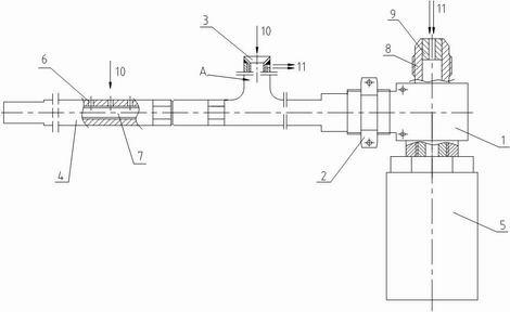
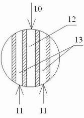
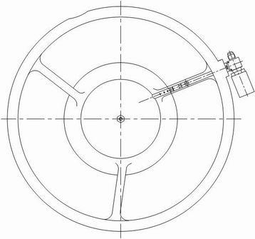
The invention discloses a device for measuring the total pressure and total temperature of air flow at an inlet of an aeromotor. The device provided by the invention is characterized by consisting of a fixed seat, a fixed nut, a total pressure tube, a total temperature tube and a pressure sensor, wherein the total temperature tube is connected with the total pressure tube through screw threads, the total pressure tube is connected with the fixed seat through threads, the fixed seat is fixed at the front edge of a rectifying support column on the inlet casing of the motor through the threads on the fixed seat by the fixed nut, and the pressure sensor is connected with an inner screw thread hole on the fixed seat through an adapter; the total temperature tube is internally provided with a precise temperature sensitive resistor; and an air-bleed tube adapter on the fixed seat 1 is provided with a flow limiter which is used for regulating the air flow introduced from the rear part of a compressor. According to the invention, not only can the measurement of the total pressure and total temperature of air flow at the inlet of a motor be realized, but also the total pressure tube can be prevented from air flow stagnation and the passageway can be prevented from being frozen.
Description
Measuring device for total pressure and total temperature of aero-engine inlet airflow technical field The invention relates to a measuring device for the total pressure and total temperature of the inlet airflow of an aeroengine. The measurement of the total temperature and total pressure at the inlet of the engine helps to accurately monitor the intake air flow of the engine so as to accurately control the fuel supply to the engine. The invention belongs to the technical field of aero-engine testing. Background technique With the development of aero-engines, the level of engine control is constantly improving. How to accurately control the engine is more important. The premise of precise control is accurate and real-time measurement, and the accurate measurement results can be fed back to the control system in time. The engine is effectively controlled, and the total temperature and total pressure of the same cross-section of the airflow at the engine inlet directly aff...
Claims
Login to View More Application Information
Patent Timeline
 Patent Type & Authority Applications(China)
IPC IPC(8): F02C7/047F02C7/04F02C7/057
Inventor 宋满祥潘宁民万科蔡万华董维安
Owner BEIHANG UNIV
Features
- R&D
- Intellectual Property
- Life Sciences
- Materials
- Tech Scout
- Unparalleled Data Quality
- Higher Quality Content
- 60% Fewer Hallucinations
Learn More Browse by: Latest US Patents, China's latest patents, Technical Efficacy Thesaurus, Application Domain, Technology Topic, Popular Technical Reports.
© 2025 PatSnap. All rights reserved.Legal|Privacy policy|Modern Slavery Act Transparency Statement|Sitemap|About US| Contact US: help@patsnap.com


