

Instantaneous counter flow type heat exchanger
A counter-flow type heat exchanger technology, applied in the direction of heat exchanger type, heat exchanger shell, indirect heat exchanger, etc., can solve the problem of unusable heat supply pipes without circulation, water flowing straight in and out without circulation, heat Water cannot be used and other problems, to achieve the effect of shortening the heat balance time, saving the heat exchange area, and saving labor costs
Inactive Publication Date: 2011-06-15
张伟
View PDF9 Cites 7 Cited by
- Summary
- Abstract
- Description
- Claims
- Application Information
AI Technical Summary
Problems solved by technology
The reason why this patented product cannot be installed vertically is that the diverter water baffle is in the cavity of the header at one end, and it is not a sealed connection, which leads to the straight in and out of the series of water without circulation, so it cannot be installed vertically
If it is installed vertically, the four pipe joints must be upward, causing the air release valve to be downward, which is easy to be blocked, and the heat supply pipe cannot be used without circulation.
In addition, floor heating is generally used for heating at present. If the pipe joint is installed vertically, it must be installed close to the ground.
Pipe joints are installed upwards, resulting in waste of installation materials and unsightly appearance
If the 4 pipe joints are installed downwards, it is easy to install, saving materials, fast and beautiful, and the tap water system does not circulate. Because the 4 pipe joints are designed on the header at one end, the water baffle is not sealed and there are gaps in the connection, and the cold water is in the cavity of the lower header Go straight in and out through the gap of the water baffle, the upper header and the hot water in the pipe form a dead angle. The whole tap water system is not heated and circulated, forming two zones of upper heat and lower cool. No hot water can be released and cannot be used.
Method used
View moreImage
Smart ImageViewing Examples

Examples
Embodiment Construction
Login to View More PUM
 Abstract
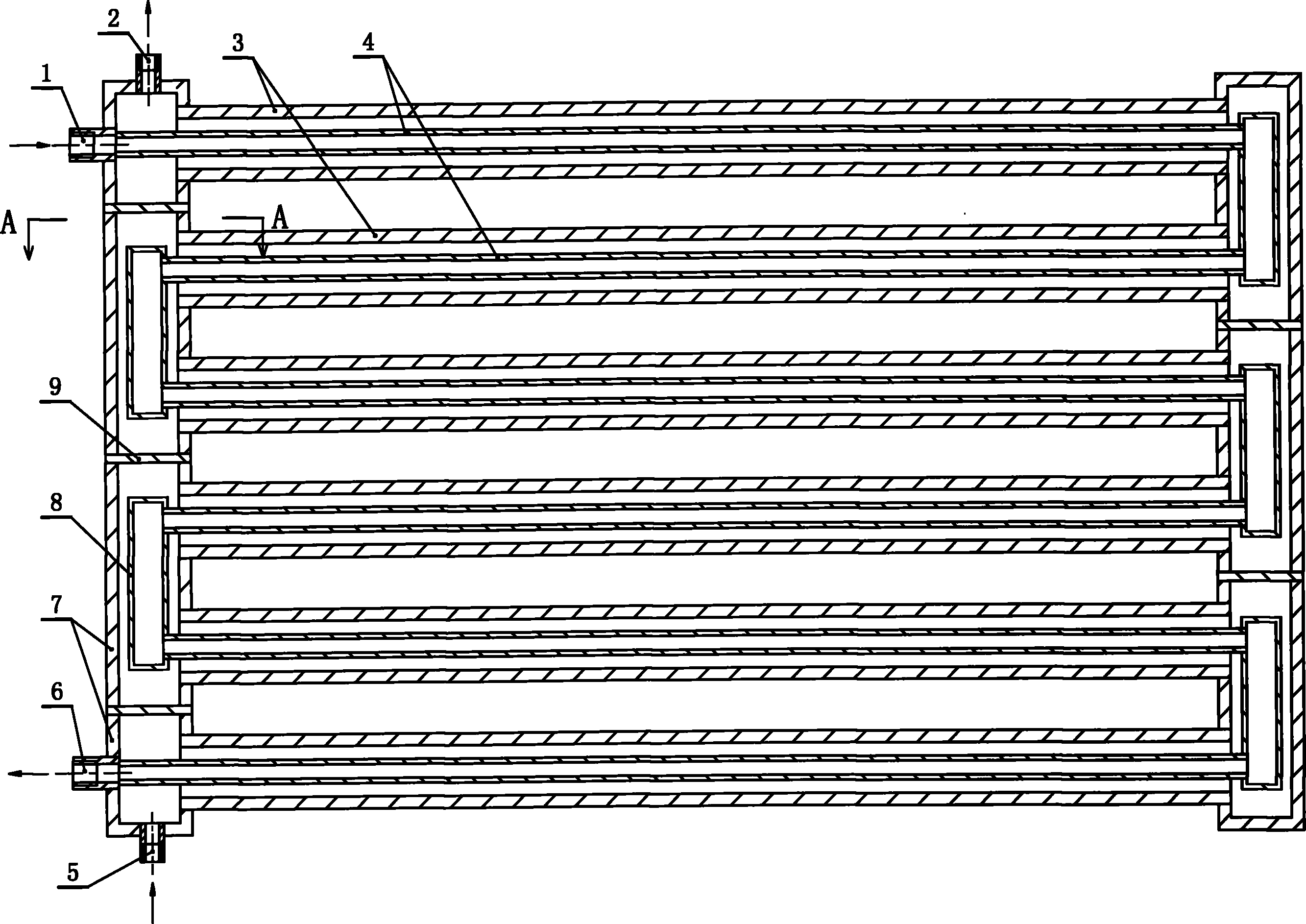
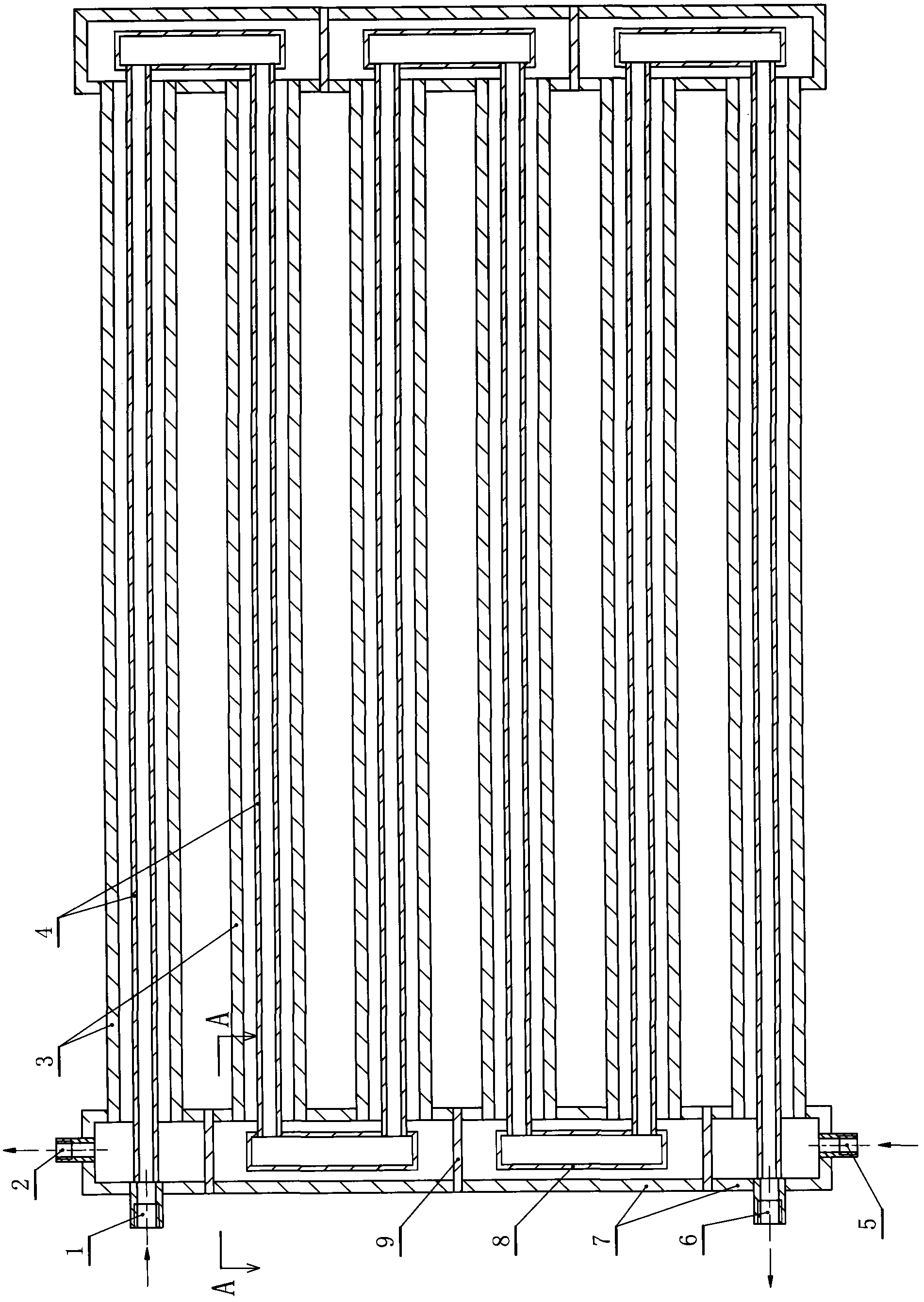
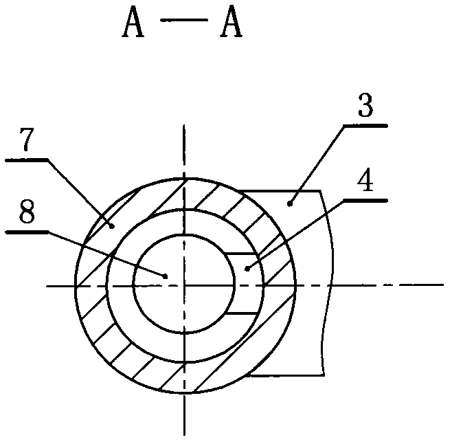
The invention relates to an instantaneous counter flow type heat exchanger which comprises a central heating water inlet, a central heating water outlet, a tap water inlet, a tap water outlet and two or more than two tap water heat absorption pipes, wherein two ends of the tap water heat absorption pipes are respectively communicated with a tap water communicating pipe; central heating supply pipes penetrate in the tap water heat absorption pipes and are communicated; one end of each communicated central heating supply pipe are connected with the central heating water inlet; and the other end of each central heating supply pipe are connected with the central heating water outlet. The instantaneous counter flow type heat exchanger is characterized in that the tap water communicating pipe is provided with one or more than one water plugging board. The heat exchanger enables a user to bathe by using a heat source of a heating pipe network, the heat absorption pipes do not scale, the cavity gap between two medium pipes is small, the cold fluid counter flows in a narrow cavity while covering a heat pipe, so that the heat conduction is quick, and the heat exchange capacity is high. The heat exchanger has the advantages of strong compression resistance, small hot fluid resistance, quick heat conduction and high efficiency, and the cold fluid counter flows in the narrow pipe cavity.
Description
Instantaneous counterflow heat exchanger technical field The invention relates to a heating heat exchanger for bathing with tap water, which is installed and used on heating pipelines of civilian households to obtain heat by exchanging heat with hot water of the heating system, especially relates to an instant heat counterflow type with fast heat conduction and large heat transfer Heat Exchanger. Background technique The applicant applied on June 10, 2008 and was authorized on June 3, 2009. After the patented product with the patent number CN200820024167.1 and the utility model name "Counterflow Heat Exchanger for Header Split Heat Storage" was put on the market, Practice has proved that there are obvious deficiencies and defects; it cannot be installed vertically; due to the limited storage of hot water in static state, it needs to wait for heating before use during bathing, and there are defects such as the inability to continuously produce hot water above 38°C for bathi...
Claims
Login to View More Application Information
Patent Timeline
 Patent Type & AuthorityApplications(China)
IPC IPC(8): F28D7/10F28F9/02F28F21/08
Inventor张冲张伟
Owner张伟