Detection method of time difference cross in use for ultrasonic flowmeter

A cross-detection and ultrasonic technology, applied in the direction of measuring flow/mass flow, liquid/fluid solid measurement, measuring devices, etc., can solve the problems of complex electronic circuits, speed difference, high time measurement accuracy, etc., and achieve the effect of low electronic circuits

Inactive Publication Date: 2007-07-25
CHINA JILIANG UNIV
View PDF0 Cites 45 Cited by
  • Summary
  • Abstract
  • Description
  • Claims
  • Application Information

AI Technical Summary

Problems solved by technology

[0017] The main problem to be solved is the speed difference ultrasonic flowmeter, especially the time measurement accuracy of the frequency difference ultrasonic flowmeter is high and the electronic circuit is complicated.

Method used

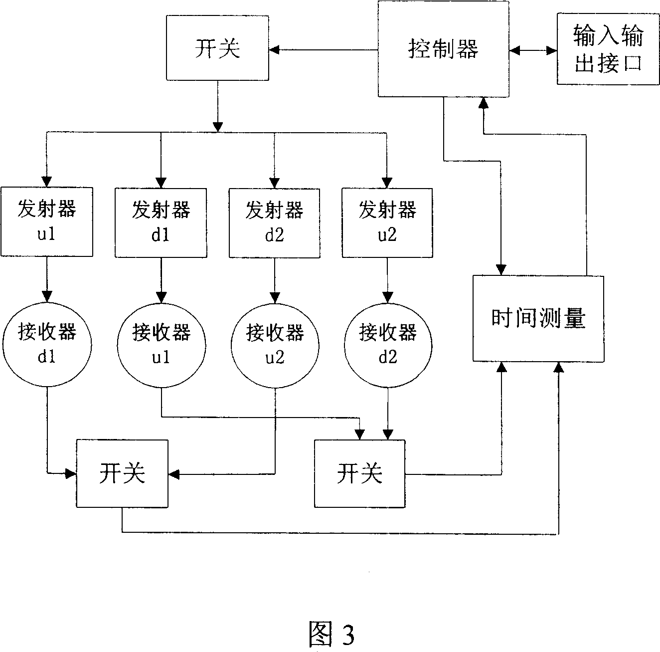

Image

  • Detection method of time difference cross in use for ultrasonic flowmeter
  • Detection method of time difference cross in use for ultrasonic flowmeter
  • Detection method of time difference cross in use for ultrasonic flowmeter

Examples


Embodiment Construction

[0032] The invention proposes a novel ultrasonic flowmeter signal detection method-the time difference cross detection method. The specific principles are as follows:

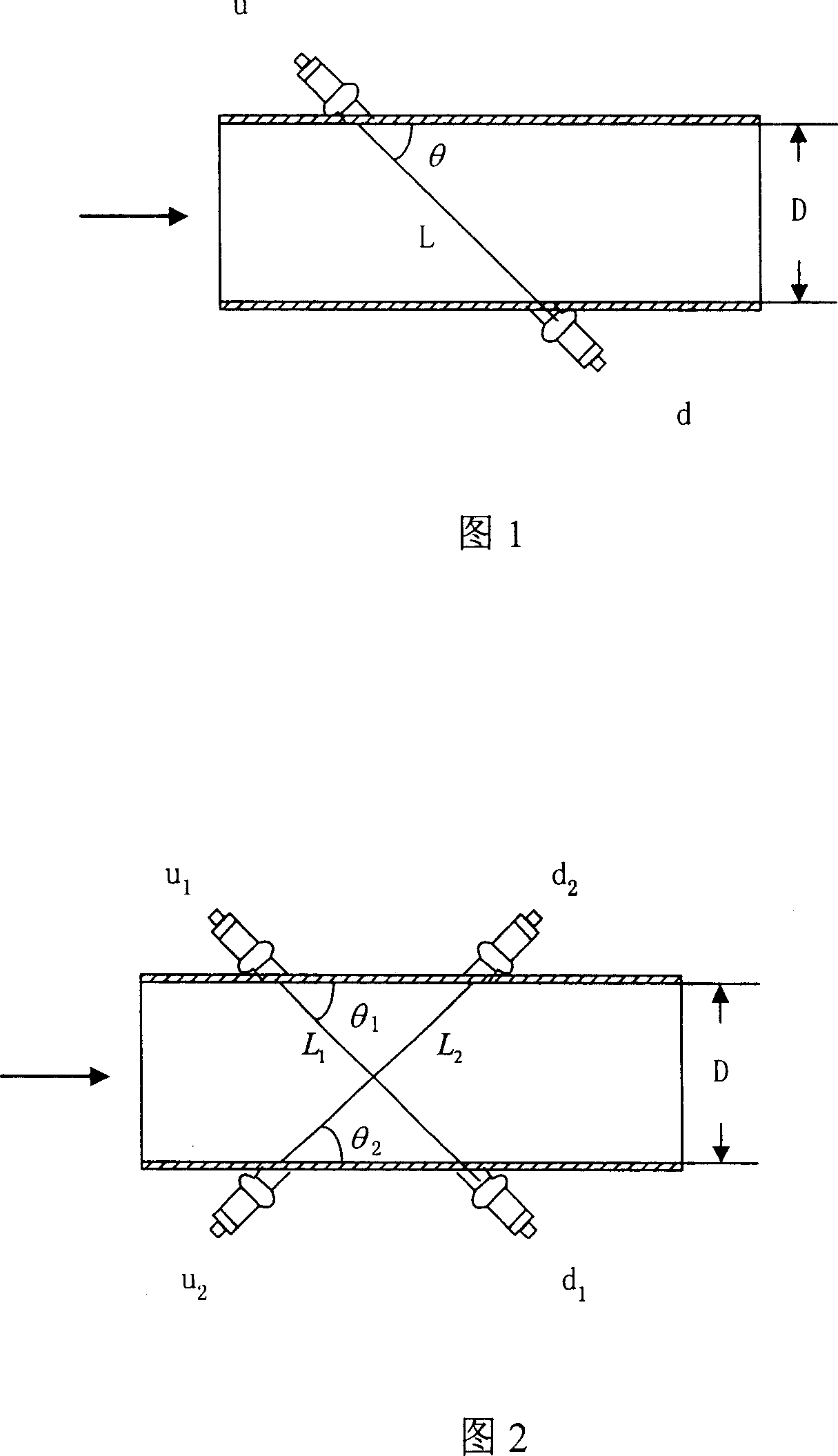
[0033] As shown in Figure 2, two pairs of ultrasonic transducers are used: transducer u 1 (upstream), transducer d 1 (downstream) and transducer u 2 (upstream), transducer d 2 (downstream), two pairs of transducers are respectively installed on both sides of the fluid pipeline with a certain distance apart, the inner diameter of the pipeline is D, the four transducers are arranged in an X shape, and the path lengths of the ultrasonic waves are L 1 and L 2 , the angle between the propagation direction of the ultrasonic wave and the flow direction of the fluid is θ 1 and θ 2 . The propagation time of ultrasonic wave downstream is t s , the countercurrent propagation time is tn .

[0034] When working, two pairs of transducers are triggered at the same time, one pair of forward flow and one pair of revers...


PUM


Abstract

A time difference cross detecting method of ultrasonic flow meter includes using two pairs of transverters as probe set to emit and receive signal, setting the first pair of transverters to be worked on forward flow mode and second pair of transverters to be worked on counter flow mode, emitting out ultrasonic ray simultaneously by probe set formed by two pairs of transverters to record thee time-differences, exchanging the working directions of two pairs of transverters and repeating above said emitting step to obtain another three time-differences.

Description

technical field [0001] The invention relates to ultrasonic flowmeter technology, in particular to a method for detecting difference crossover of ultrasonic flowmeter. Background technique [0002] Compared with mechanical flowmeters and electromagnetic flowmeters, ultrasonic flowmeters have many advantages, such as high measurement accuracy, strong adaptability to pipe diameter, non-contact measurement, convenient use and easy digital management. With the development of piezoelectric ceramic technology, electronic technology and high-speed digital processing technology, the performance of ultrasonic flowmeters has been greatly improved, the manufacturing cost has been greatly reduced, and the scope of application of ultrasonic flowmeters has been expanded. By the end of the 1990s, ultrasonic flowmeters in Gain considerable advantages in the field of gas flow measurement. [0003] According to the principle of signal detection, the current ultrasonic flowmeter can be roughly...

Claims


Application Information

Patent Timeline
Patent Type & Authority Applications(China)
IPC IPC(8): G01F1/66
Inventor 苏中地张洪军梁国伟
Owner CHINA JILIANG UNIV
Why Eureka
Try Eureka