Turbine BOAS with edge cooling

a technology of edge cooling and turbine boas, which is applied in the direction of machines/engines, liquid fuel engines, mechanical devices, etc., can solve the problems of shortening the life of parts and reducing the efficiency of turbines

Inactive Publication Date: 2011-11-22
FLORIDA TURBINE TECH
View PDF17 Cites 46 Cited by
  • Summary
  • Abstract
  • Description
  • Claims
  • Application Information

AI Technical Summary

Benefits of technology

[0007]It is another object of the present invention to provide for a turbine BOAS in which the drilled holes are eliminated.

Problems solved by technology

Excess hot gas leakage flowing through this gap will decrease the turbine efficiency and lead to hot spots on the blade tip and shroud segment in which oxidation can develop and therefore shorten the life of the parts.

Method used


Image

  • Turbine BOAS with edge cooling
  • Turbine BOAS with edge cooling
  • Turbine BOAS with edge cooling

Examples


Embodiment Construction

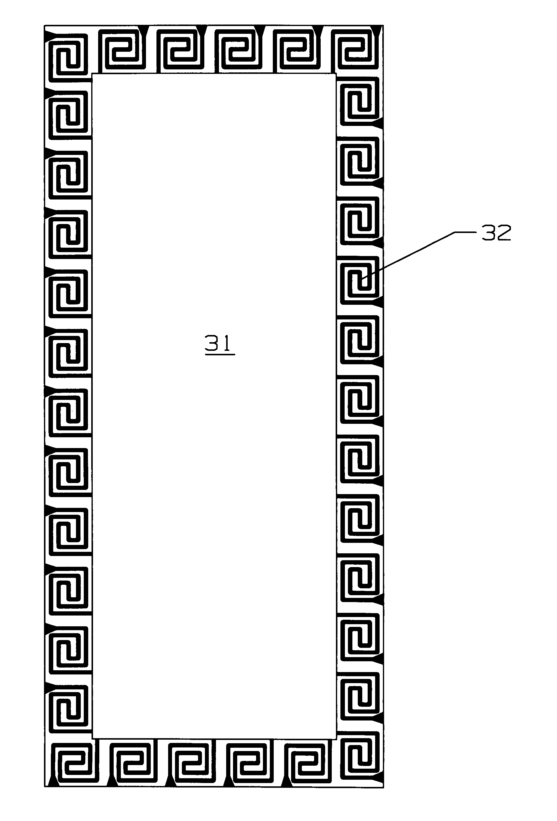
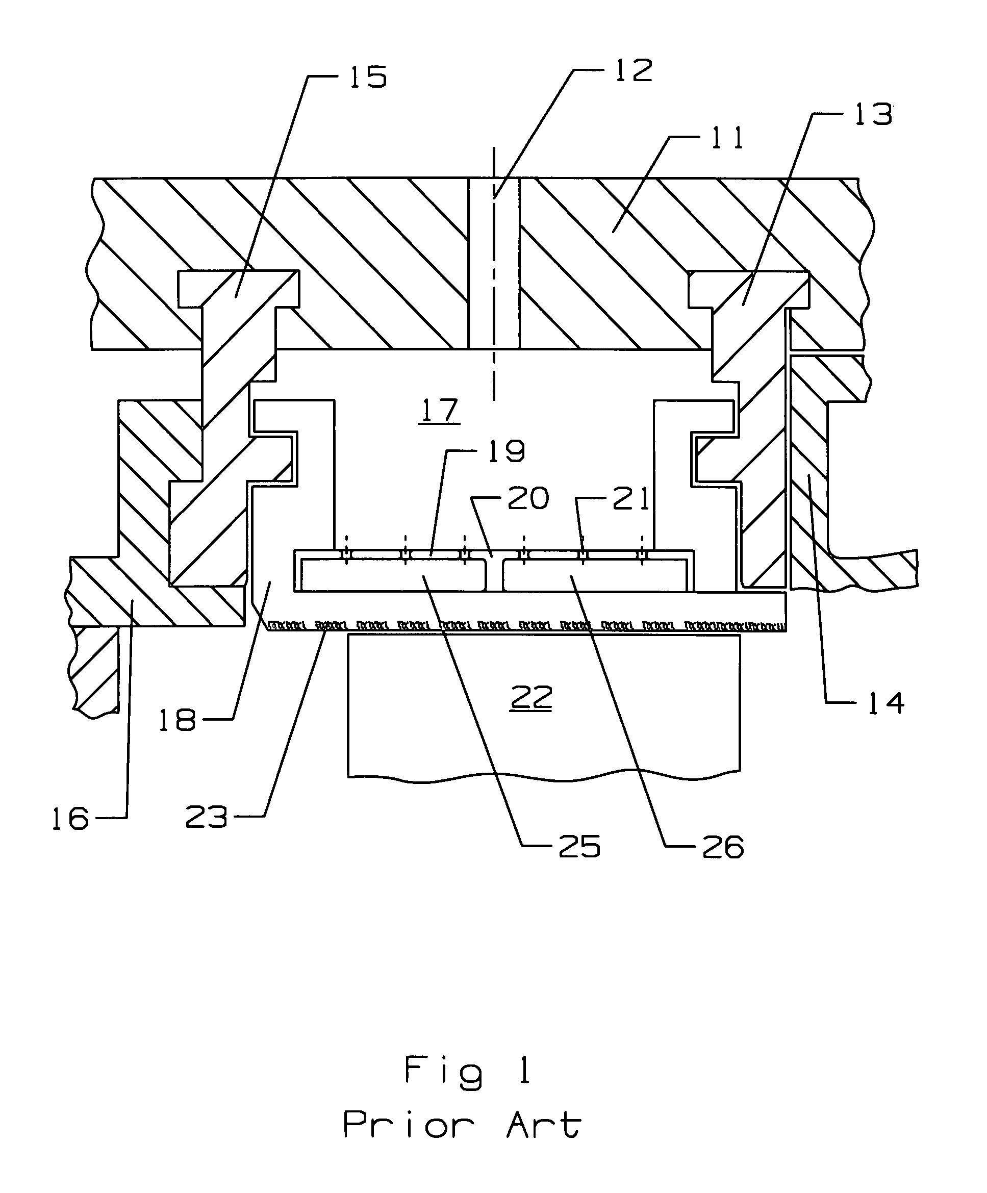
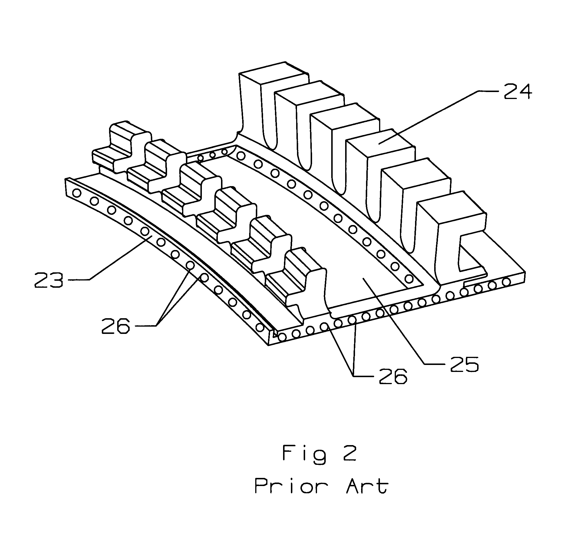
[0018]The present invention is a BOAS (blade outer air seal) for a gas turbine engine in which a plurality of shroud segments form the BOAS with tips of the rotor blades. The BOAS of the present invention includes a plurality of counter flowing micro serpentine flow cooling circuits spaced around the four edges of the shroud segments. The BOAS of the present invention can take the form of the prior art BOAS, as in FIGS. 1 and 2, but with the drilled holes replaced by the counter flowing micro serpentine flow cooling circuits.

[0019]FIG. 3 shows a cross section top view of one of the shroud segments that form the BOAS, and includes an impingement area 31 within the four edges of the shroud segment. A plurality of the counter flowing micro serpentine flow cooling circuits 32 are spaced around the four edges as seen in FIG. 3. Each of the micro circuits 32 include an inlet that opens into the impingement area 31 so that the spent cooling air can flow into the micro circuits 32. The micr...


PUM


Abstract

A cooling hole having an inlet passage forming an inward spiral flow path and an outlet passage forming an outward spiral flow path in which the two paths are counter flowing in order to improve the heat transfer coefficient. The spiral cooling hole is used in a blade outer air seal (BOAS) for a turbine in which the edges of the shroud segments include a counter flowing micro serpentine flow cooling circuit with thin diffusion discharge cooling slots for the BOAS edges. The total BOAS cooling air is impingement from the BOAS cooling air manifold and metered through the impingement cooling holes to produce impingement cooling onto the backside of the BOAS. The spent cooling air is then channels into the multiple micro serpentine cooling flow circuits located around the four edges of the shroud segments. This cooling air then flows in a serpentine path through the horizontal serpentine flow channels and then discharged through the thin diffusion cooling slots as peripheral purge air for the mate faces as well as the spacing around the BOAS or shroud segments. Trip strips are used in the serpentine flow channels for the augmentation of internal heat transfer cooling capability. The micro serpentine flow cooling air circuits spaced around the four edges of the shroud segments are formed into the shroud segments during the casting process of the shroud segments.

Description

BACKGROUND OF THE INVENTION[0001]1. Field of the Invention[0002]The present invention relates generally to a gas turbine engine, and more specifically to a blade outer air seal with cooling of the edges.[0003]2. Description of the Related Art including information disclosed under 37 CFR 1.97 and 1.98[0004]In a gas turbine engine, the turbine includes at least on stage of rotor blades that include blade tips that form a seal with an outer shroud of the engine. A gap or space is formed between the blade tip and the inner surface of the shroud in which hot gas leakage can flow. The outer shroud is formed of a plurality of shroud segments that together form a full 360 degree annular configuration around the rotating blades. Excess hot gas leakage flowing through this gap will decrease the turbine efficiency and lead to hot spots on the blade tip and shroud segment in which oxidation can develop and therefore shorten the life of the parts.[0005]In the prior art of gas turbine engines, a ...

Claims


Application Information

Patent Timeline
Patent Type & Authority Patents(United States)
IPC IPC(8): F01D11/08
CPCF01D11/08F05D2250/185F05D2240/11F05D2260/201F05D2260/221
Inventor LIANG, GEORGE
Owner FLORIDA TURBINE TECH
Why Eureka
Try Eureka