Video monitor data transmission system

A data transmission system and video surveillance technology, which is applied in the field of video surveillance data transmission system, can solve the problems of mutual influence of access points, low transmission efficiency, limited number of transmission video channels, etc., and achieve the goal of improving transmission capacity and simplifying transmission lines Effect

Active Publication Date: 2011-06-15
深圳市诺龙技术股份有限公司
View PDF3 Cites 14 Cited by
  • Summary
  • Abstract
  • Description
  • Claims
  • Application Information

AI Technical Summary

Problems solved by technology

Optical fiber transmission is a general method to solve the transmission problem at present, but the optical fiber transmits uncompressed video data, and under the same total bandwidth, the number of transmission video channels is very limited
If an Ethernet switch with an optical fiber interface is u

Method used


Image

  • Video monitor data transmission system
  • Video monitor data transmission system
  • Video monitor data transmission system

Examples


Example Embodiment

[0026] Example 1

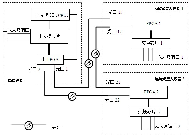
[0027] Video surveillance data transmission systems with open serial transmission links, such as Figure 5 As shown, it includes a central office device, a remote optical access device 1, a remote optical access device 2, a remote optical access device 3 . . . The optical port of the central office device is connected to the optical port 11 of the remote optical access device 1 through optical fibers, and the optical port 12 of the remote optical access device 1 is connected to the optical port 21 of the remote optical access device 2 through optical fibers. The optical port 22 of the optical access device 2 is connected to the optical port 31 of the remote optical access device 3 through an optical fiber, and so on, to form a serial open serial transmission link. The working principle steps are as follows:

[0028] Step 1: The central office equipment is responsible for maintaining the time slot allocation table. When the central office equipment is pow...

Example Embodiment

[0035] Example 2

[0036] Video surveillance data transmission system with ring network link, such as Image 6 As shown, it includes a central office device, a remote optical access device 1, a remote optical access device 2, a remote optical access device 3, and a remote optical access device 4. The optical port 1 of the central office device is connected to the optical port 11 of the remote optical access device 1 through optical fibers, and the optical port 12 of the remote optical access device 1 is connected to the optical port 21 of the remote optical access device 2 through optical fibers. The optical port 22 of the remote optical access device 2 is connected to the optical port 31 of the remote optical access device 3 through optical fibers, and the optical port 32 of the remote optical access device 3 is connected to the optical port 41 of the remote optical access device 4 through optical fibers. . The optical port 42 of the remote optical access device 4 is conne...


PUM


Abstract

The invention belongs to the field of video monitor and discloses a video monitor data transmission system which comprises an optical fiber, a local end equipment and a plurality of remote optical access equipments, wherein the optical fiber, the local end equipment and the plurality of remote optical access equipments form an open serial link or a ring network link used for transferring compressed video service data or other ethernet service data. In the video monitor data transmission system, a time division multiplexing technology is adopted to transfer ethernet data of the plurality of remote optical access equipments through a same optical fiber, thereby greatly simplifying a transmission line; and the video monitor data transmission system can realize automatic distribution of time slots and coordinate a plurality of remote optical access units to normally work with the local end equipment.

Description

technical field [0001] The invention belongs to the field of video monitoring, and in particular relates to a video monitoring data transmission system. Background technique [0002] With the development of video surveillance technology, the video surveillance business needs to solve the problem of long-distance transmission of video sources on the one hand, and the problem of video data networking on the other hand. Optical fiber transmission is a common method to solve the transmission problem at present, but the number of transmission video channels is very limited when the total bandwidth is the same for the uncompressed video data transmitted by optical fiber. If an Ethernet switch with an optical fiber interface is used for transmission, due to the inherent characteristics of Ethernet technology such as the Ethernet collision detection mechanism and the shared bandwidth of all access points, the transmission efficiency will be low during heavy-load data transmission. ...

Claims


Application Information

Patent Timeline
IPC IPC(8): G08C23/06H04N7/18
Inventor 张顺庆
Owner 深圳市诺龙技术股份有限公司
Why Eureka
Try Eureka