Load lock chamber

A sampling chamber and vacuum technology, applied in electrical components, semiconductor/solid-state device manufacturing, circuits, etc., can solve problems such as bending and cracking of the main body of the vacuum sampling chamber

Inactive Publication Date: 2013-06-26
TES CO LTD
View PDF5 Cites 0 Cited by
  • Summary
  • Abstract
  • Description
  • Claims
  • Application Information

AI Technical Summary

Problems solved by technology

[0005] However, in a vacuum chamber having a structure in which two or more unit cells are stacked, the pressure difference between the unit cells may cause deformation such as bending
In particular, as the area of ​​the substrate to be processed increases, the load chamber also becomes larger, which causes greater deformation of the load chamber with the above-mentioned structure, and in severe cases, even the main body of the load chamber may be deformed. Cracking and other issues

Method used


Image

  • Load lock chamber
  • Load lock chamber
  • Load lock chamber

Examples


Embodiment Construction

[0028] Hereinafter, preferred embodiments of the present invention will be described in detail with reference to the accompanying drawings. The above features and effects of the present invention will become clearer through the following detailed description in conjunction with the accompanying drawings, and those skilled in the art of the present invention can easily implement the technical idea of ​​the present invention. The present invention is not limited to the following embodiments, but can be realized in other ways. The role of each embodiment described in this specification is to disclose the technical content more completely and fully convey the technical ideas and features of the present invention to those skilled in the art. In the drawings, in order to clearly illustrate the present invention, the thickness of each device or film (layer) and region is exaggerated, and each device may include various additional devices not described in this specification.

[0029]...


PUM


Abstract

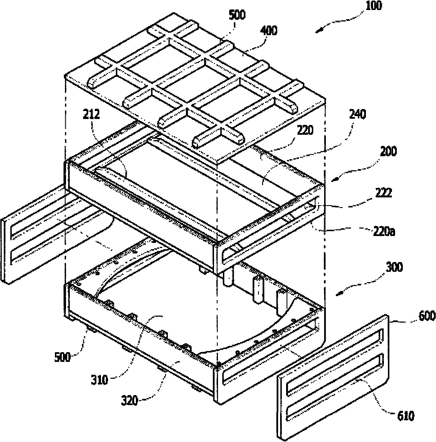
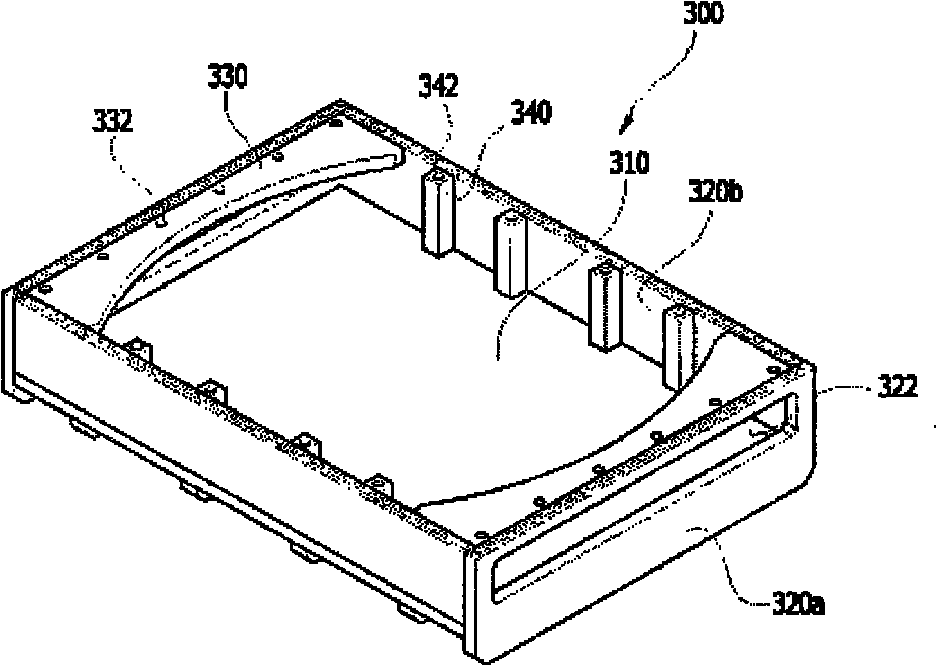
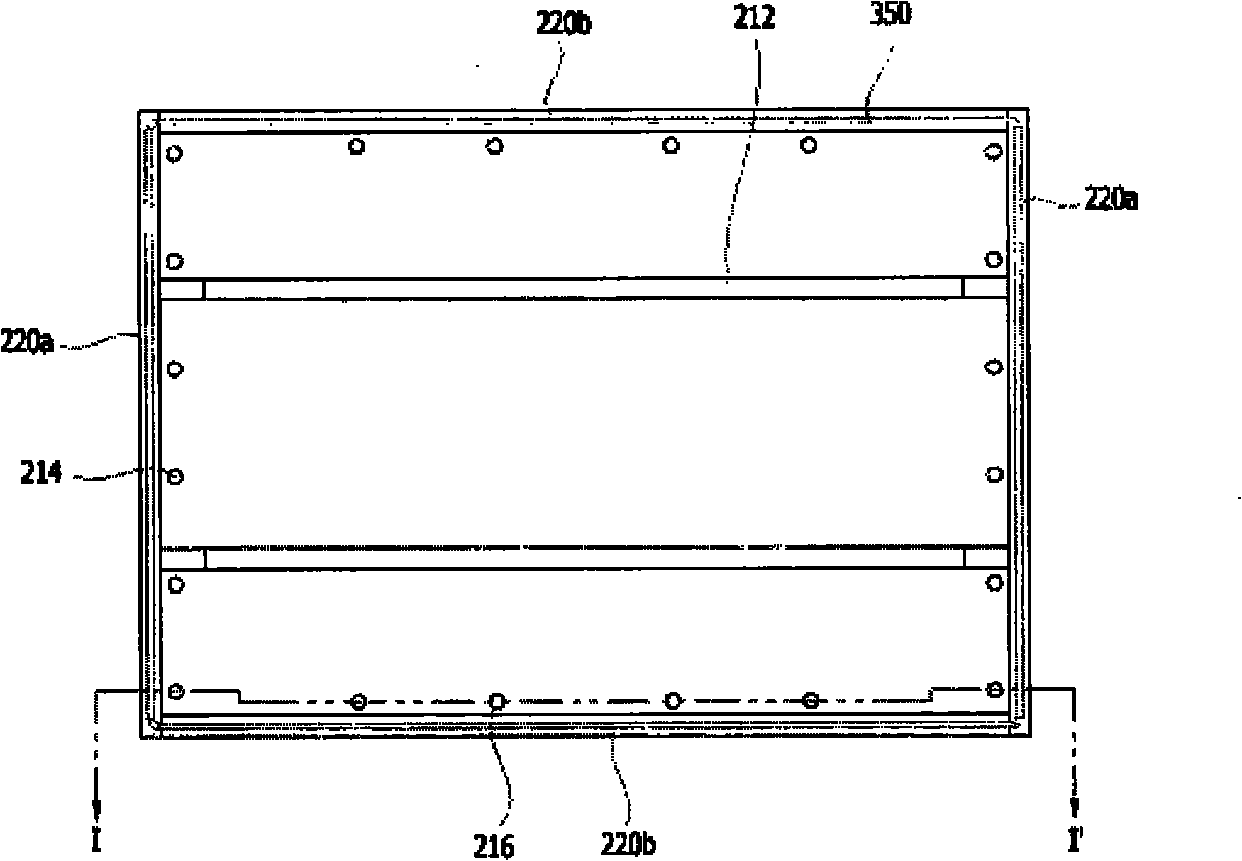
The invention provides a load lock chamber capable of preventing vacuum from deformation. The load lock chamber comprises a first chamber, a second chamber and a top cover. The first chamber comprises a first bottom plate and four first side walls vertically extending from the first bottom plate, on two first side walls oppositely disposed, a first slot channel used for moving in and moving out abase plate is formed. The second chamber comprises a second bottom plate and four second side walls vertically extending from the second bottom plate, what's more, the second chamber combines the first chamber in a mode of making an upper part in an opening shape be located at a side of the first chamber. On two second side walls oppositely disposed, a second slot channel used for moving in and moving out the base plate is formed. The second chamber comprises a first reinforcing rib extending from the upper ends of the two second side walls provided with the second slot channel to the internal sides. The top cover covers the opening-shaped upper part of the first chamber, preventing vacuum deformation caused by pressure differences between laminated unit chambers to a great extent.

Description

technical field [0001] The present invention relates to a vacuum loading chamber (load lock chamber, also referred to as "load fixing chamber" or "loading / unloading chamber"), more specifically, before and after performing a large-area processed substrate process, Vacuum load chamber for loading and unloading substrates to be processed. Background technique [0002] Generally speaking, when manufacturing products such as liquid crystal display devices and solar cells, it is necessary to perform various manufacturing processes such as depositing various thin films on substrates such as glass substrates and patterning the deposited thin films. And these processes are done in processing chambers that provide optimum conditions for the execution of the respective processes. Especially recently, a substrate processing system in which a plurality of processing chambers are arranged in a cluster structure so as to process a plurality of substrates in a short period of time is wide...

Claims


Application Information

Patent Timeline
Patent Type & Authority Patents(China)
IPC IPC(8): H01L21/00
CPCH01L21/67201
Inventor 李敦熙金范城河周一马熙铨金东建卢东珉
Owner TES CO LTD
Why Eureka
Try Eureka