Medium supporting structure applied to radio-frequency coaxial connector

A support structure, radio frequency coaxial technology, applied in the direction of connection, two-part connection device, fixed/insulated contact member, etc., to achieve the effect of increasing the volume ratio and reducing the effective dielectric constant

Inactive Publication Date: 2011-06-15
SUZHOU HUAZHAN SPACE APPLIANCE
View PDF7 Cites 3 Cited by
  • Summary
  • Abstract
  • Description
  • Claims
  • Application Information

AI Technical Summary

Problems solved by technology

However, they have more or less defects and problems in further reducing the effective dielectric constant of the dielectric support section, simple and efficient realization of high-precision assembly, or cost control.

Method used


Image

  • Medium supporting structure applied to radio-frequency coaxial connector
  • Medium supporting structure applied to radio-frequency coaxial connector
  • Medium supporting structure applied to radio-frequency coaxial connector

Examples


Embodiment 1

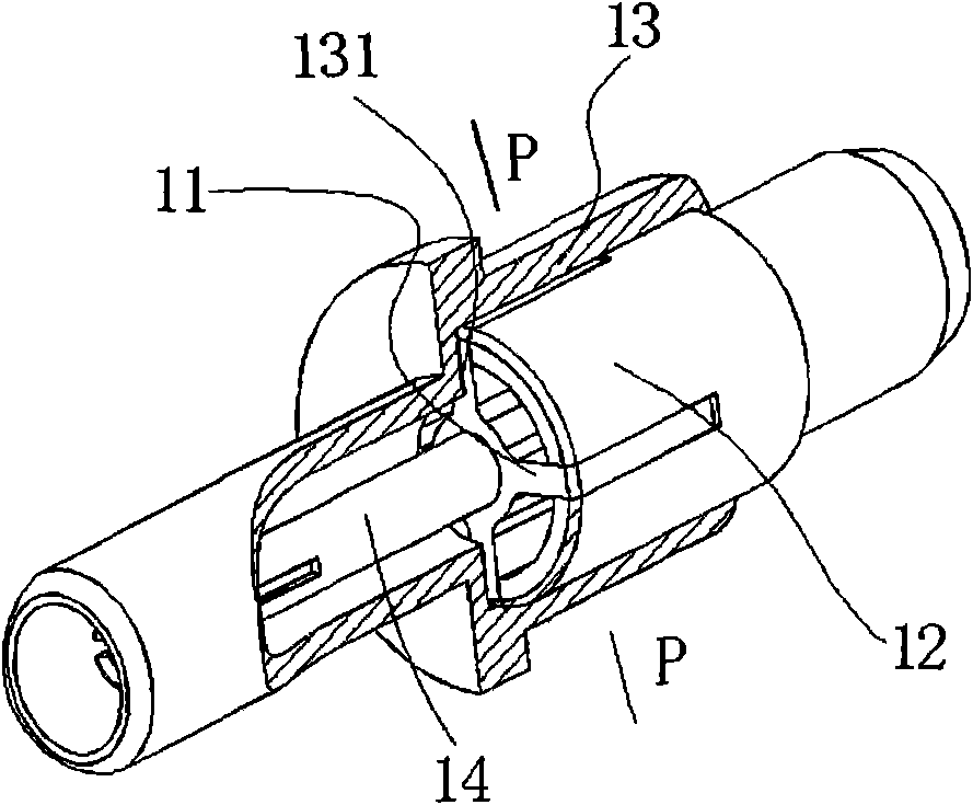
[0023] Such as figure 1 As shown, a dielectric support structure applied to a radio frequency coaxial connector includes an insulating support 11, a first positioning structure 13, and a second positioning structure.

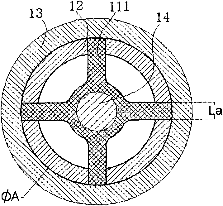
[0024] In order to reduce the effective dielectric constant of the dielectric support to a greater extent, the insulating support 11 is designed with a plurality of thin-walled insulating support ribs 111 . The insulating support member 11 of this embodiment has four thin-walled insulating support ribs 111, the four thin-walled insulating support ribs 111 are of equal length, and the insulating support member 11 is a cross-shaped structure with a hole in the center.

[0025] In this embodiment, the second positioning structure is the slotted positioning structure 12, and the first positioning structure 13 may be the outer conductor of the coaxial connector.

[0026] Such as image 3 As mentioned above, the groove width La of the slotted positioning structure 1...

Embodiment 2

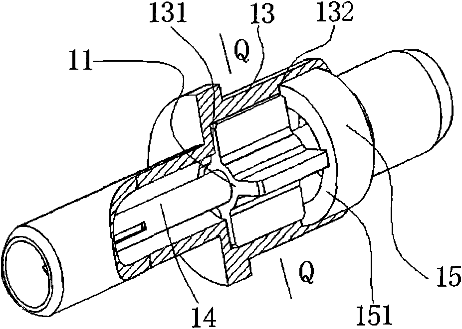
[0030] The difference between this embodiment and the first embodiment is that: for the application of the medium support structure where the degree of freedom of rotation does not need to be limited, the second positioning structure can be selected as the non-slotted positioning structure 15, such as figure 2 , Figure 4 shown.

[0031] At this time, the distance La between the axial positioning planes 131 and 132 of the first positioning structure 13 is consistent with the length Lb of the insulating support 11. After being installed in place, the insulating support 11 is placed on the axial positioning plane 131 of the first positioning structure 13 and 132, then the positioning plane 151 of the positioning structure 15 without slots coincides with the axial positioning plane 132 of the first positioning structure 13 to define the axial degree of freedom of the insulating support 11, and then through riveting and interference and other ways to fix their relative positions...

Embodiment 3

[0033] The difference between this embodiment and the first embodiment is that the groove depth of the slot 121 of the slotted positioning structure 12 is shorter than the length of the thin-walled insulating support rib 111 . The limitation of this structure and the limitation of degrees of freedom can refer to the situation of the first embodiment.

[0034] In terms of design, the groove width La of the slotted positioning structure 12 is consistent with the wall thickness La of the thin-walled insulating support rib 111, and the slot depth Lb of the slotted positioning structure 12 is consistent with the length Lb of the thin-walled insulating support rib 111. When the thin-walled insulating support rib 111 snaps into the slotted positioning structure 12, the slot width La of the slotted positioning structure 12 defines the degree of freedom of rotation of the insulating support 11, and the groove bottom plane 1211 of the slotted positioning structure 12 is in line with the ...


PUM


Abstract

The invention discloses a medium supporting structure applied to a radio-frequency coaxial connector, comprising an insulation supporting piece, a first positioning structural piece and a second positioning structural piece. The first positioning structural piece is arranged outside the insulation supporting piece to limit the radial freedom degree of the insulation supporting piece, the first positioning structural piece and the second positioning structural piece are matched and fixed from both ends of the insulation supporting piece to limit the axial freedom degree of the insulation support piece, the insulation supporting piece comprises a plurality of thin-walled insulation supporting ribs, an inner hole for inserting an inner conductor of the coaxial connector is arranged in the center of the insulation supporting piece, a circle is formed on the outer margin of the plurality of thin-walled insulation supporting ribs of the insulation supporting piece and is structurally coaxial with the inner hole, and the internal diameter of the inner hole of the insulation supporting piece is consistent with the diameter of the part which the inner conductor is inserted into the inner hole. The invention can greatly increase the volume ratio between air and the insulation medium in the medium supporting segment and remarkably decrease the effective SIC (Specific Inductive Capacity) of the medium supporting segment on the premise that the mechanical strength is ensured.

Description

technical field [0001] The invention relates to a dielectric support structure applied to a radio frequency / microwave coaxial connector. Background technique [0002] The dielectric support of the coaxial connector is a very important part of the coaxial connector, and its shape, structure and physical properties (such as dielectric constant, mechanical properties, etc.) will affect its performance. Considering that the transmission impedance of the connector is closely related to the effective dielectric constant of the dielectric support, the effective dielectric constant should be reduced as much as possible when designing the dielectric support—especially in the field of high-frequency (such as millimeter wave) transmission. The commonly used method is Drill holes and dig grooves on the medium to form a mixed medium support of air and medium materials. There are already various structures and patents in the industry around related structures supported by mixed media. F...

Claims


Application Information

Patent Timeline
Patent Type & Authority Applications(China)
IPC IPC(8): H01R13/40H01R24/40
Inventor 肖顺群
Owner SUZHOU HUAZHAN SPACE APPLIANCE
Why Eureka
Try Eureka