Shielded magnetic plug-in lock

A technology of magnetic lock and shielding plate, applied in the magnetic field, can solve problems such as poor touch feeling, and achieve the effect of soft touch and strong mechanical interlocking

Active Publication Date: 2011-06-15
FIDLOCK GMBH
View PDF5 Cites 5 Cited by
  • Summary
  • Abstract
  • Description
  • Claims
  • Application Information

AI Technical Summary

Problems solved by technology

[0008] In this regard, the operator must concentrate and also apply a certain amount of force in order to insert the plug between the magnetic north poles into the socket, which is considered a very bad touch

Method used


Image

  • Shielded magnetic plug-in lock
  • Shielded magnetic plug-in lock
  • Shielded magnetic plug-in lock

Examples


Embodiment Construction

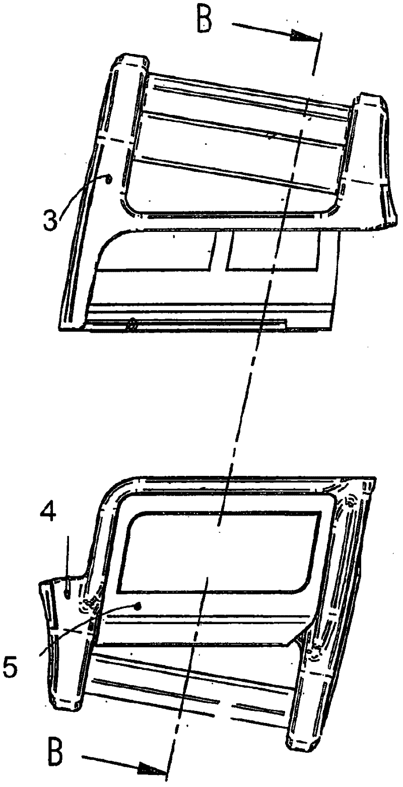
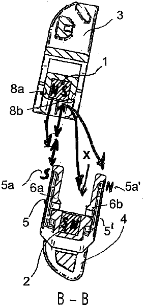
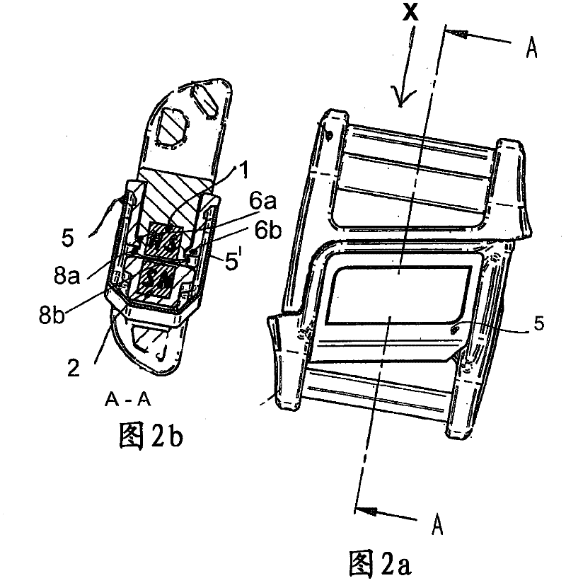
[0036] Figure 1a shows a front view of a magnetic closure according to the invention, and Figure 1b A sectional view B-B is shown. Rod magnets are identified with 1 and 2, they are in Figure 1a Extends across the width of the magnetic closure shown in and in this example has a square cross-section. Magnetization is marked with N as the north pole and S as the south pole. The magnetization runs transversely to the closing direction X along which the plug 3 is inserted into the plug receptacle 4 , and in this case the spring locking means consisting of the locking projections 8 a , 8 b and the elastic spring locking projections 6 a , 6 b is locked. locking. Figure 2a , b shows the plugged-in state, where the plug 3 is inserted into the plug receptacle 4 , wherein the magnets 1 , 2 are attracted together with opposite polarities.

[0037] The problem solved by the present invention should at first be by means of such as Figure 3a , b, a comparative example explanation ...


PUM


Abstract

The invention relates to a shielded magnetic lock that does not damage or negatively affect magnetically sensitive instruments or objects such as credit cards, pacemakers, magnetic data memories or magnetic tapes, especially to a magnetic plug-in lock, for which a connector is plugged into a connector receiving element and held therein by magnetic holding forces or, additionally, by means of mechanical engagement. According to the invention, the connector (3) and the connector receiving element (4) are designed in such a way that the connector magnet (1) and the magnet (2) for the connector receiving element are magnetised transversally to the closing direction X, and at least one shielding plate (5) consisting of a ferromagnetic material is provided on the plug or the plug receiving element. The shielding plate covers the connector magnets and the connector receiving element magnets, and the ferromagnetic material and the thickness of the shielding plate are selected in such a way asto obtain a magnetic shielding sufficient for a pre-determined use.

Description

technical field [0001] The present invention relates to a shielded magnetic closure which does not damage or is not expected to affect magnetically sensitive instruments or objects such as credit cards, pacemakers, magnetic data storage or magnetic tapes, and in particular to a A magnetic closure, in which a plug is inserted into a plug receptacle and held there by a magnetic holding force or additionally by means of a mechanical locking device. Background technique [0002] A special group of closures of this type is characterized in that, for closing, the two closure halves are plugged together in the closure direction, wherein the magnets arranged in the closure halves attract each other, but To open, the two closure halves are not suddenly pulled apart again in the direction opposite to the closure direction, but are slowly moved sideways away from each other in the direction of opening. Thus a pleasant tactile sensation is obtained. Herein, tactile sensation is unders...

Claims


Application Information

Patent Timeline
Patent Type & Authority Applications(China)
IPC IPC(8): A44B11/25
CPCH01F7/0263A45C13/1069A44D2203/00A44B11/25Y10T24/45995Y10T24/45178Y10T24/45775Y10T24/45524Y10T24/32
Inventor 约阿希姆·菲德勒
Owner FIDLOCK GMBH
Why Eureka
Try Eureka