
Radio-based activation and deactivation of a zero-energy standby mode of automation systems

A technology using radio and standby mode, applied in the field of zero-energy standby mode, to achieve the effect of prolonging continuous working time, avoiding mechanical wear and reducing maintenance costs

Inactive Publication Date: 2011-06-15
SIEMENS AG
View PDF3 Cites 7 Cited by
  • Summary
  • Abstract
  • Description
  • Claims
  • Application Information

AI Technical Summary

Problems solved by technology

However, using the above method can only activate the RFID tag itself

Method used


Image

  • Radio-based activation and deactivation of a zero-energy standby mode of automation systems
  • Radio-based activation and deactivation of a zero-energy standby mode of automation systems
  • Radio-based activation and deactivation of a zero-energy standby mode of automation systems

Examples


Embodiment Construction

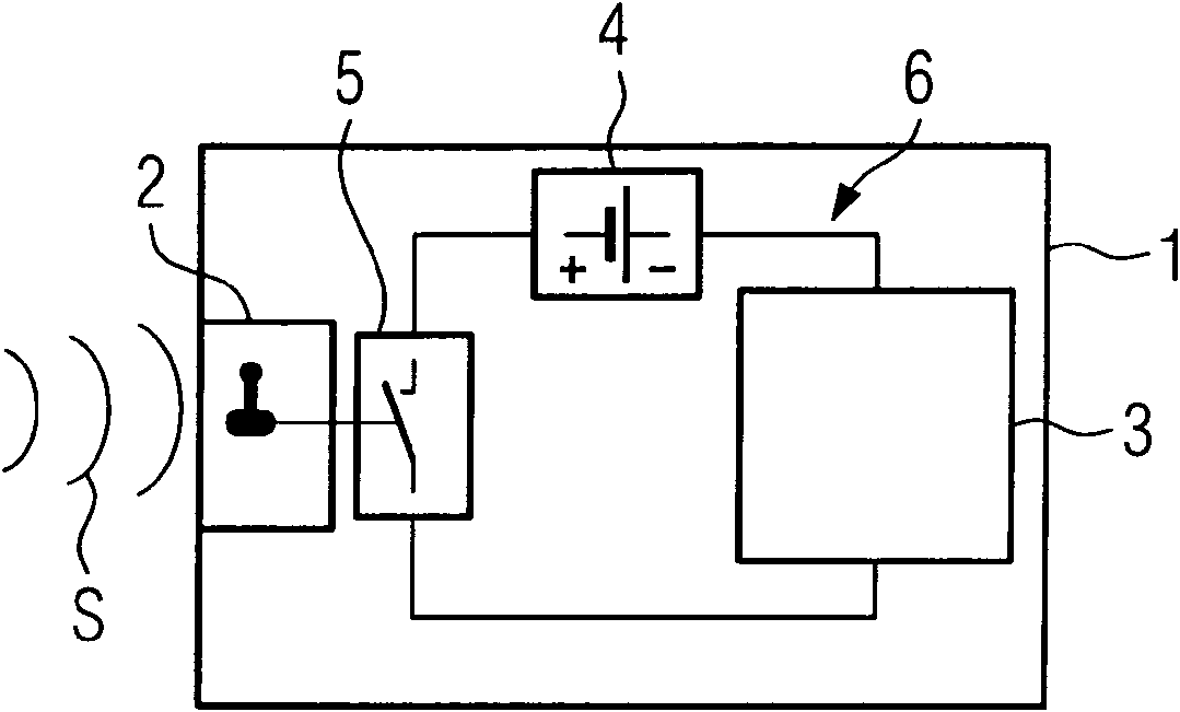
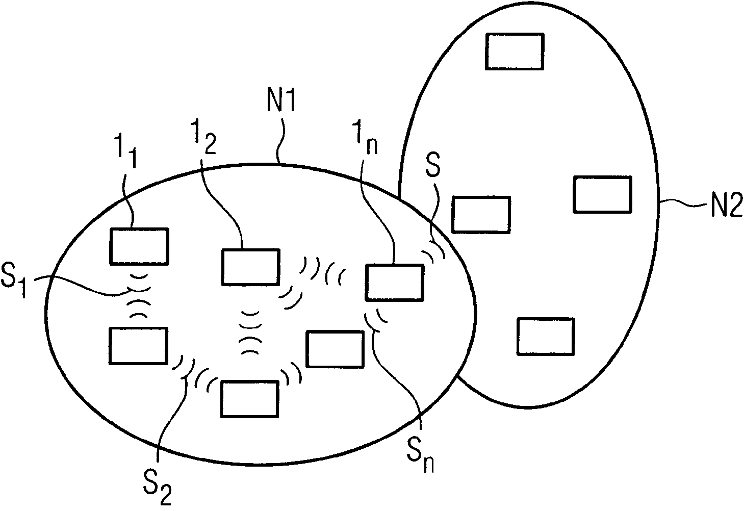
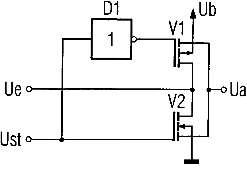
[0027] figure 1Shown is a block diagram of the electrical automation component 1. This automation component has a functional unit 3 and a passive unit 2 . The functional units are used to perform automation tasks. This functional unit is, for example, a sensor or an actuator. The functional units need to be powered to perform their tasks. This power supply is provided directly by the automation component 1 . In the present exemplary embodiment, this is the local power supply 4 , which is designed, for example, as a battery. The functional unit is supplied with the necessary electrical energy by the power supply 4 . A switch 5 is provided in the circuit 6 formed by the functional unit and the battery. This switch is an electronic switch (for example a CMOS switch), that is to say a switch designed, for example, as a semiconductor element. Once opened, this electronic switch stops the power supply to the functional unit. The functional unit then enters a standby mode tha...


PUM


Abstract

The invention relates to a method for radio-based activation and deactivation of a zero-energy standby mode of automation components, wherein a passive unit of the automation component receives a radio signal, energy transmitted with the radio signal is converted into energy for actuating an electronic switch, and an energy supply of a functional unit of the automation component is interrupted or restored by the actuation of the electronic switch, whereby the functional unit of the automation component is activated or deactivated.

Description

technical field [0001] The invention relates to a method for activating and deactivating a zero-energy standby mode of an automation component by radio and an electrical automation component. Background technique [0002] An automation system has various automation components for carrying out automation technology tasks. These components can be, for example, sensors, actuators, controls or drives. As with all electrical or electronic equipment, automation components must be powered in order for them to perform their tasks. With a few exceptions, they are generally powered by cable, radio, or batteries. Taking steps to reduce the energy consumption of electrical and electronic equipment is welcome for two reasons. On the one hand, the rising cost of electricity drives us to save electricity consumption, and on the other hand, the need to keep the maintenance costs of components that rely on batteries to be as low as possible. [0003] Especially radio-based and battery-po...

Claims


Application Information

Patent Timeline
Patent Type & Authority Applications(China)
IPC IPC(8): G05B19/042G06F1/32
CPCG05B2219/25289G05B2219/25279G05B2219/25286G05B19/0423
Inventor 延斯·克得莱斯约尔格·奈迪格
Owner SIEMENS AG
Learn More