Cup for soya-bean milk making machine and soya-bean milk making machine using same

A soymilk maker and cup technology, which is applied in the field of soymilk maker, can solve the problems that the manufacturing cost of soymilk maker cannot be minimized, the cup structure of soymilk maker is complex, and the deflector is not easy to clean, so as to achieve good crushing effect and save diversion Organ structure, the effect of retaining nutrients

Inactive Publication Date: 2011-06-22
彭亚军 +2
View PDF0 Cites 4 Cited by
  • Summary
  • Abstract
  • Description
  • Claims
  • Application Information

AI Technical Summary

Problems solved by technology

However, for the soymilk maker with this structure, the installation structure of the deflector and the bottom of the cup must be considered, which makes the structure of the cup of the soymilk machine slightly complicated, and the manufacturing cost of the soymilk maker cannot be reduced to Lowest, in addition, the deflector is not easy to clean, it is inconvenient to use, and the cutting is not efficient enough

Method used


Image

  • Cup for soya-bean milk making machine and soya-bean milk making machine using same
  • Cup for soya-bean milk making machine and soya-bean milk making machine using same
  • Cup for soya-bean milk making machine and soya-bean milk making machine using same

Examples


Embodiment 1

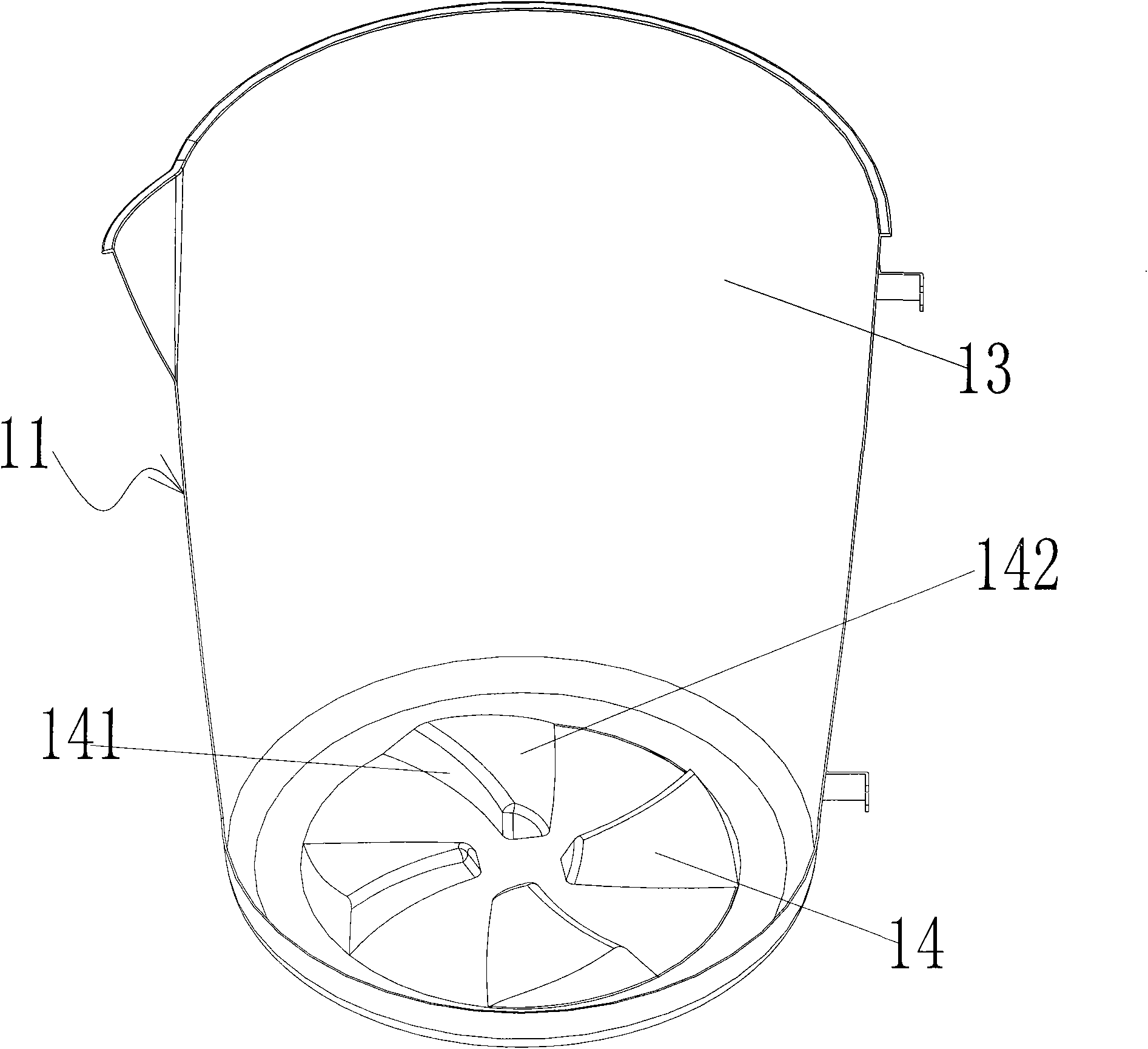
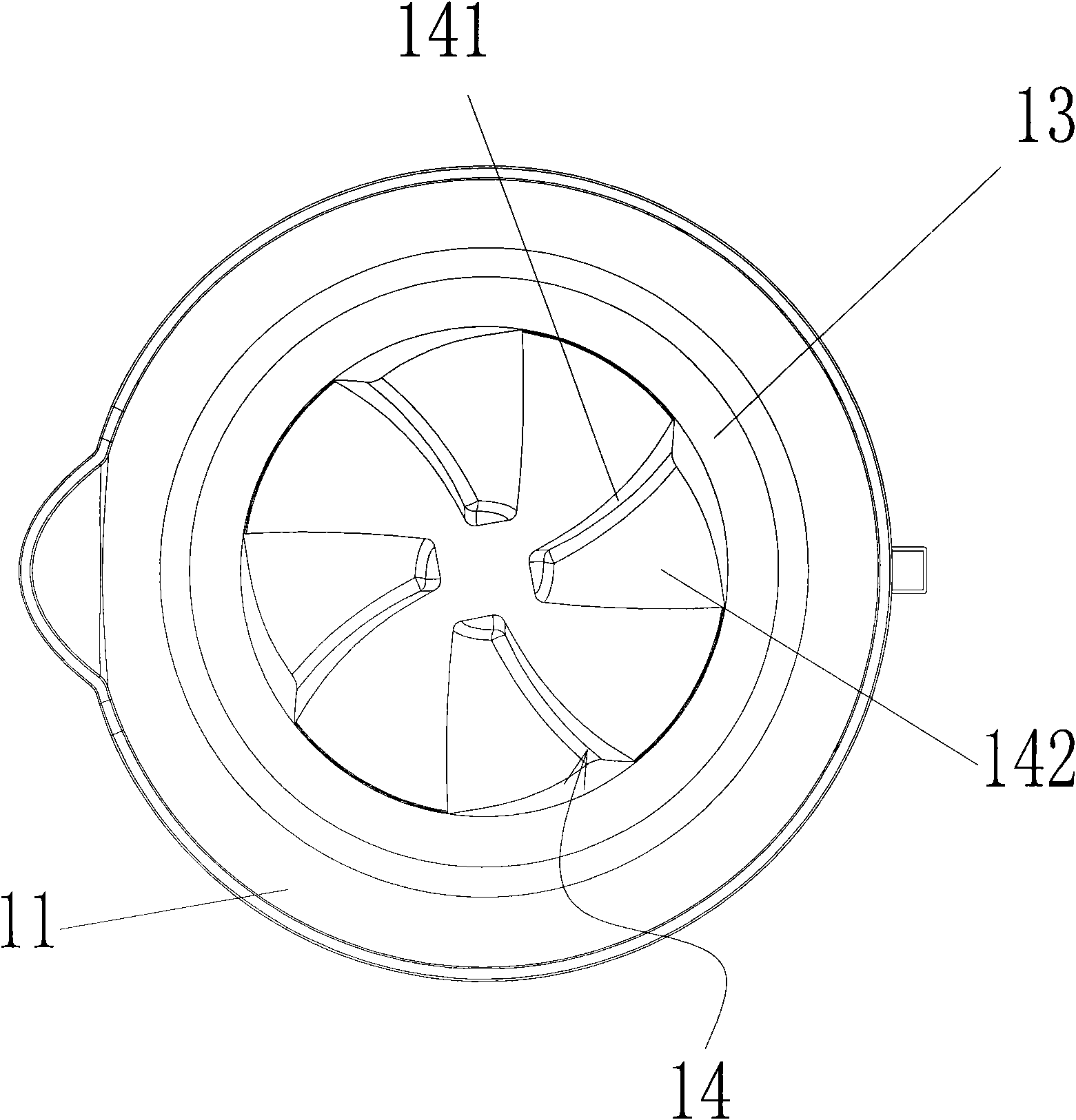
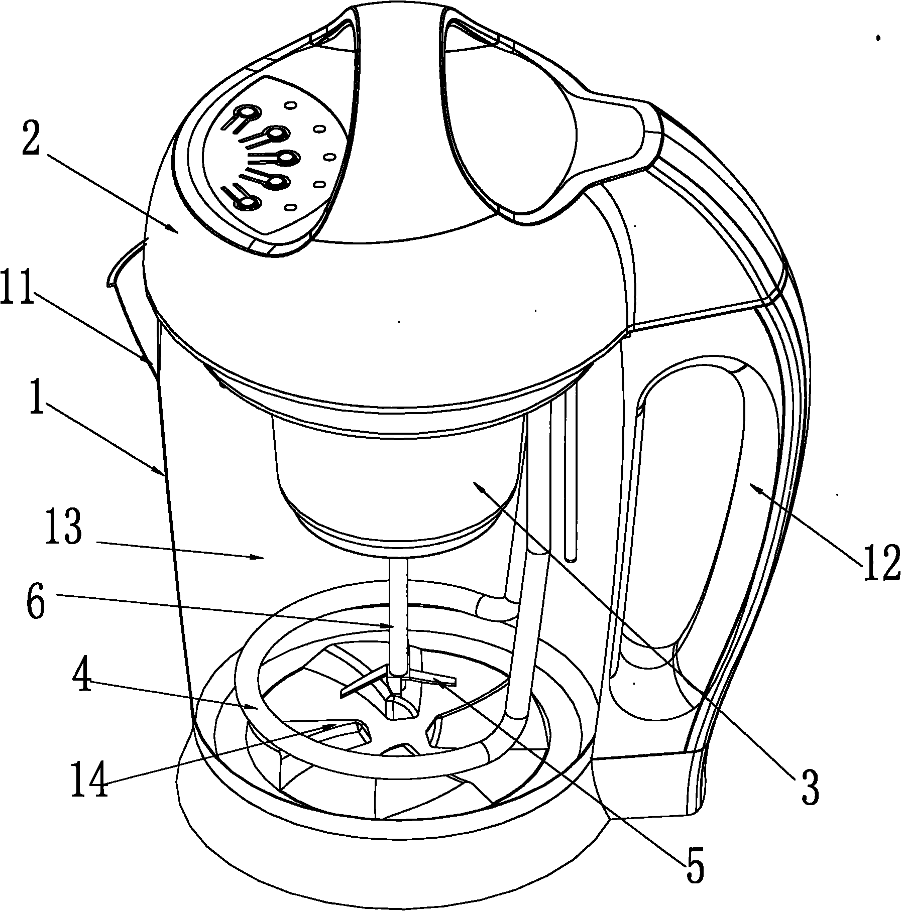
[0026] Embodiment one: if figure 1 , figure 2 , image 3 , Figure 4 As shown, the soybean milk machine of the present invention includes a cup 1 and a cup cover 2 installed on the cup. The cup 1 includes a cup body 11 and a handle 12. A cutting cavity 13 is formed on the cup body 11. Soymilk is arranged in the cup cover 2. Machine control circuit board 8, motor 3, the crushing blade 5 that is installed on the motor output shaft 6, the motor output shaft 6 and the crushing blade 5 stretch into the inside of the cutting cavity 13, at the bottom of the cavity 13, on the bottom surface of the cup body 11 Four guide vanes 14 are protruded, and the crushing blade 5 positioned above the guide vanes 14 rotates to form a forward vortex during operation, while the guide vanes 14 form a reverse vortex. A heat pipe 4 protrudes from the cup cover 2 to the cutting cavity 13, and the heat pipe 4 is electrically connected with the control circuit board 8 of the soybean milk machine. An ...

Embodiment 2

[0027] Embodiment two: if Figure 5 As shown, the difference from Embodiment 1 is that there are three guide vanes 14 on the inner bottom surface of the cup 1 .

Embodiment 3

[0028] Embodiment three: as Image 6 As shown, the difference from Embodiment 1 is that there are five guide vanes 14 on the inner bottom surface of the cup 1 .


PUM


Abstract

The invention relates to a cup for a soya-bean milk making machine, which comprises a cup body and a handle, wherein a cutting cavity is formed on the cup body. The cup is characterized in that a plurality of guide vanes are bulged at the bottom of the cavity and on the bottom surface of the cup body. The soya-bean milk making machine using the cup comprises the cup and a cup cover arranged on the cup, wherein the cup comprises the cup body and the handle; the cutting cavity is formed on the cup body; a control circuit board of the soya-bean milk making machine, a motor and a crushing blade arranged on a motor output shaft are arranged in the cup cover; and the motor output shaft and the crushing blade extend into the cutting cavity. The soya-bean milk making machine is characterized in that the plurality of guide vanes are bulged at the bottom of the cavity and on the bottom surface of the cup body; during operation, the crushing blade positioned above the guide vanes rotates to form a forward vortex, and the guide vanes form a reverse vortex. The soya-bean milk making machine has a good effect, crushed slurry is mixed with soya-bean milk, so that abundant nutritional ingredients can be reserved; and a fluid director can be saved, a structure is simpler, and the manufacturing cost is reduced greatly.

Description

Technical field: [0001] The invention relates to a soybean milk machine cup and an applied soybean milk machine. Background technique: [0002] Existing soya-bean milk machine generally comprises cup body, cup cover, is located on cup cover and stretches into the motor of cup body, is located at the pulverizing blade on the output shaft of motor and a filter net cover, and described pulverizing blade is placed in filter Inside the grille. When in use, put beans between the net cover and the blade, add clean water, and drive the crushing blade by the motor to crush the beans, and finally make soybean milk. The soymilk machine with this structure has defects such as uneven crushing of beans, the blocking of slurry in the filter screen cover so that the nutrient content of soybean milk is reduced, and the filter screen is inconvenient to clean. [0003] In order to solve the above technical problems, a soymilk machine with a deflector uses a deflector to replace the filter sc...

Claims


Application Information

Patent Timeline
Patent Type & Authority Applications(China)
IPC IPC(8): A47J31/44A23C11/10A23L11/60
Inventor 彭亚军曹安民许卓永
Owner 彭亚军
Why Eureka
Try Eureka