Ultrasonic vibration screen and method for filtering and screening powder by using same

A vibrating screen and ultrasonic technology, which is applied in the fields of filtering, chemical instruments and methods, and solid separation, can solve problems such as low work efficiency, difficulty in cleaning, broken screen, etc., and achieve high work efficiency, small vibration amplitude, The effect of high vibration frequency

Inactive Publication Date: 2011-06-22
YU TUNG ZHONGSHAN ENG
View PDF1 Cites 7 Cited by
  • Summary
  • Abstract
  • Description
  • Claims
  • Application Information

AI Technical Summary

Problems solved by technology

The ultrasonic vibrating screen has the following defects when filtering and screening powder: 1. Because the ultrasonic vibrating head and the electric wires connected to it are exposed above the screen, so when filtering and screening powder, the ultrasonic vibrating head and the electric wires connected to it will be powdered Covering, no

Method used


Image

  • Ultrasonic vibration screen and method for filtering and screening powder by using same
  • Ultrasonic vibration screen and method for filtering and screening powder by using same
  • Ultrasonic vibration screen and method for filtering and screening powder by using same

Examples


Embodiment 1

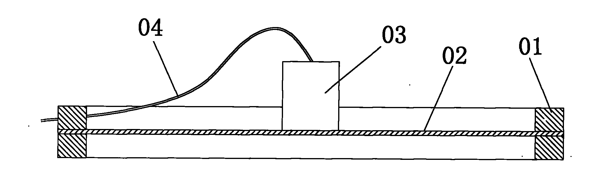
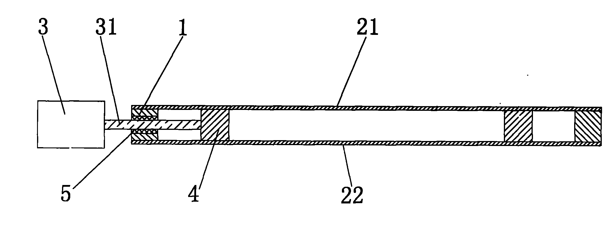
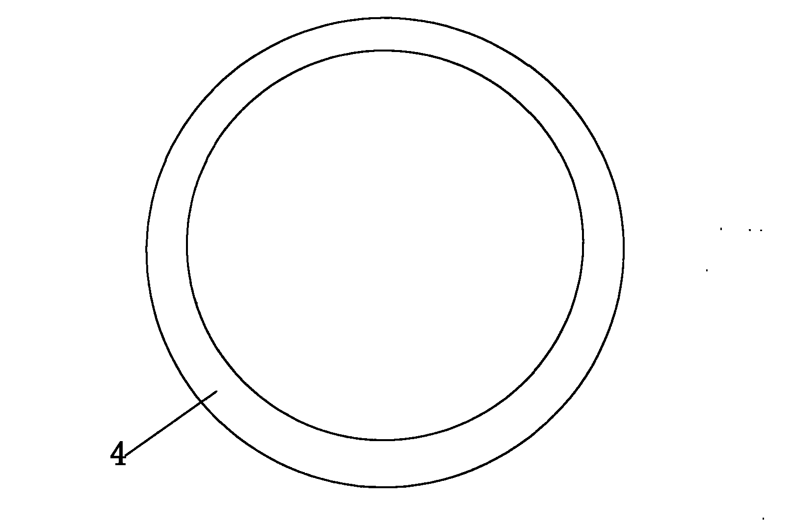
[0017] Embodiment one: if figure 2 , image 3 As shown, a kind of ultrasonic vibrating screen comprises a support 1, an upper screen 21 and a lower screen 22 arranged on the support 1 and an ultrasonic vibrating head 3, and the ultrasonic vibrating head 3 is arranged on the outside of the support 1. The ultrasonic vibration head 3 has a vibration transmission shaft 31, and a shaft hole is provided between the upper screen 21 and the lower screen 22 on the support 1. The vibration transmission shaft 31 is inserted into the shaft hole from the outside of the support 1 and makes the vibration transmission shaft The end passes through the shaft hole, and the end of the vibration transmission shaft 31 is connected with a vibration ring 4 made of elastic material. The vibration ring 4 is arranged between the upper screen 21 and the lower screen 22 and is pasted on the lower and lower screens. The surface of the vibration transmission shaft 31 and the shaft hole is provided with a ...

Embodiment 2

[0019] Embodiment two, such as Figure 4 As shown, the difference from the first implementation is that only the upper screen 21 is provided on the support, and the vibrating ring 4 is screwed with the connecting piece 6 provided on the surface of the upper screen 21 through a bolt 7, so as to use The vibrating ring 4 is fixed below the surface of the upper screen cloth 21 .


PUM


Abstract

The invention relates to an ultrasonic vibration screen. The ultrasonic vibration screen comprises a bracket, a screen and an ultrasonic vibration head, wherein the screen is arranged on the bracket; the ultrasonic vibration head is arranged on the outer side of the bracket; the ultrasonic vibration head is provided with a vibration-transmitting shaft; a shaft hole is formed on the bracket; the vibration-transmitting shaft is inserted into the shaft hole from the outer side of the bracket and the end part of the vibration-transmitting shaft passes through the shaft hole; the end part of the vibration-transmitting shaft is connected with a vibration ring; and the vibration ring is close to the surface of the screen. A method for filtering and screening powder by using the ultrasonic vibration screen is characterized in that: the ultrasonic vibration head separated from the screen transmits vibration generated by the ultrasonic vibration head to the vibration ring through the vibration-transmitting shaft; and the vibration ring acts on the screen, so that the screen is vibrated up and down, large-particle powder is isolated by the screen, small-particle powder penetrates the screen, and the powder can be filtered and screened. By the ultrasonic vibration screen and the method for filtering and screening the powder by using the same, working efficiency is high; the screen is easy to clean and is difficult to break through vibration; and service life is long.

Description

Technical field: [0001] The invention relates to an ultrasonic vibrating screen and a method for filtering and screening powder. Background technique: [0002] The existing ultrasonic vibrating screen generally includes a support 01, a screen 02 with a mesh on the support 01, and an ultrasonic vibrating head 03 located at the center of the screen 02. The ultrasonic vibrating head 03 is provided with a power supply Connect the wire 04 as shown in picture 1. The ultrasonic vibrating screen has the following defects when filtering and screening powder: 1. Because the ultrasonic vibrating head and the electric wires connected to it are exposed above the screen, so when filtering and screening powder, the ultrasonic vibrating head and the electric wires connected to it will be powdered Covering, not easy to clean; 2. The ultrasonic vibrating head will heat up during the working process, resulting in solidification of the powder and low work efficiency; 3. The ultrasonic vibratin...

Claims


Application Information

Patent Timeline
IPC IPC(8): B07B1/28B07B1/46
Inventor 柯儒群
Owner YU TUNG ZHONGSHAN ENG
Why Eureka
Try Eureka