Heat recovery system for vehicle

A heat recovery, heat absorption technology, used in vehicle components, heating/cooling equipment, electromechanical devices, etc.

Inactive Publication Date: 2011-06-29
TOYOTA IND CORP
View PDF6 Cites 4 Cited by
  • Summary
  • Abstract
  • Description
  • Claims
  • Application Information

AI Technical Summary

Problems solved by technology

The stator core is wound with coils

Method used


Image

  • Heat recovery system for vehicle
  • Heat recovery system for vehicle
  • Heat recovery system for vehicle

Examples


Embodiment Construction

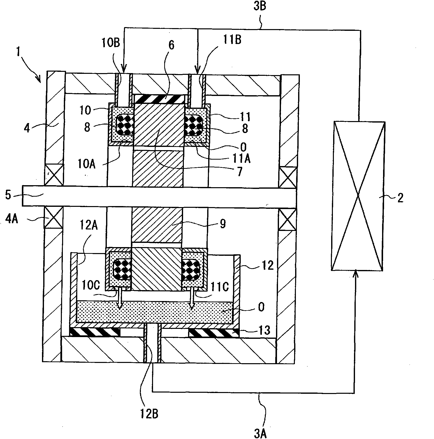
[0026] refer to Figure 1 to Figure 4 , the heat recovery system according to the first embodiment of the present invention for a vehicle will be described below.

[0027] refer to figure 1 , the heat recovery system includes a motor 1 as an electric rotating device, a heat exchanger 2 and pipes 3A, 3B. The pipes 3A, 3B connect the motor 1 to the heat exchanger 2 and enable oil O as a first heat exchange medium to flow between the motor 1 and the heat exchanger 2 .

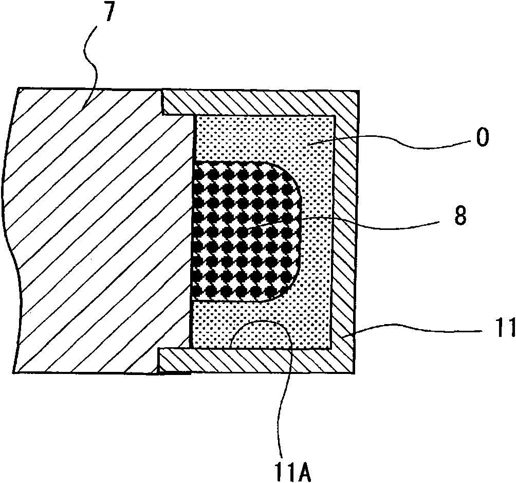
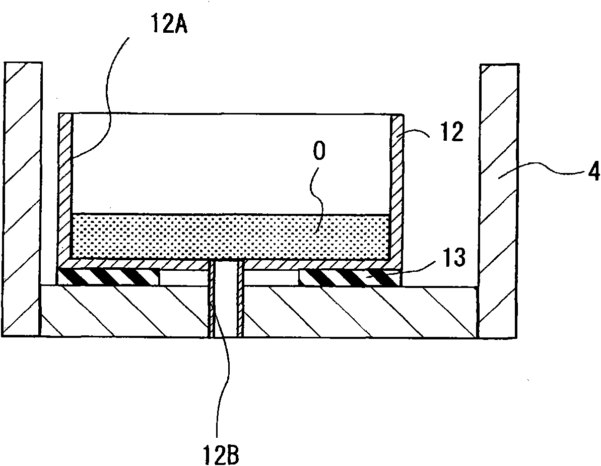
[0028] The motor 1 has a housing 4 and a rotary shaft 5 rotatably supported by the housing 4 via a bearing 4A. The stator core 7 is fixed to the inner periphery of the case 4 via the heat insulator 6 as an auxiliary heat insulator portion. Rubber is used as a material for the heat insulator 6 . The stator core 7 has a plurality of slots equiangularly spaced and extending in the axial direction of the stator core 7 , and the coils 8 are wound in these slots of the stator core 7 . Inside the stator core 7 , a r...


PUM


Abstract

Provided is a heat recovery system for a vehicle. The heat recovery system includes an electric rotary device, a heat exchanger, a pipe and a reservoir. The electric rotary device has a stator core and a housing. The stator core is wounded with a coil. The heat exchanger provides heat exchanging between first and second heat medium. The first heat medium is in contact with the coil and absorbs heat from the coil. The pipe connects the electric rotary device to the heat exchanger and transfers the first heat medium. The reservoir is formed in the housing and stores the first heat medium. The electric rotary device has an insulative body. The insulative body prevents heat of the first heat medium from being dissipated outside of the housing.

Description

technical field [0001] The invention relates to a heat recovery system for a vehicle. Background technique [0002] Japanese Patent Application Publication No. 2008-148464 discloses a motor for driving wheels. The motor has a stator core and a rotor in a housing of the motor. Coils are wound around the stator core, and the rotor is mounted on the shaft of the motor. An annular sheath is secured to the stator core on opposite sides of the stator core at a location adjacent the coils. Oil passages for cooling the coils are formed in each sheath. The jacket has formed therein inlets and outlets for the oil passages, and pipes are connected to the inlets and outlets. The case can store oil flowing out from the outlet of the oil passage. At the bottom of the housing another pipe is connected. A pump for circulating the oil and a storage tank for storing the oil are connected to the pipe. [0003] However, in the above-mentioned motor, the heat recovered from the coil by th...

Claims


Application Information

Patent Timeline
Patent Type & Authority Applications(China)
IPC IPC(8): B60H1/00H02K9/19
CPCH02K9/19H02K9/197
Inventor 安谷屋拓深作博史横町尚也铃木润也川口真广
Owner TOYOTA IND CORP
Why Eureka
Try Eureka