
Liquid crystal display device

a technology of liquid crystal display and display device, which is applied in the direction of optics, instruments, optical elements, etc., can solve the problems of difficult to perfectly remove the lamp image, complex manufacturing process, and thin liquid crystal televisions, so as to prevent heat emitted from light sources, improve the brightness of an observer side, and efficiently emitted

Inactive Publication Date: 2011-10-18
TOPPAN PRINTING CO LTD
View PDF13 Cites 2 Cited by
  • Summary
  • Abstract
  • Description
  • Claims
  • Application Information

AI Technical Summary

Benefits of technology

The solution effectively reduces lamp image effects, ensures uniform light emission, and prevents warpage due to heat, while maintaining high brightness and simplifying the manufacturing process by integrating the optical film and device as a single unit, improving the overall performance and reliability of the display device.

Problems solved by technology

In addition, year by year, liquid crystal televisions are becoming thinner.
However, it is difficult to perfectly remove the lamp image.
Therefore, a manufacturing process may become complex.
Further, a lens sheet arranged on a diffusion plate and a liquid crystal pixel may cause moire interference.
However, in a type using an under diffusion film and a light diffusion film, the number of components is increased, thereby processes in manufacturing a display become complex and dust becomes mixed between optical sheets.
However, in a backlight unit using such an optical film, because it is necessary that a light outgoing surface of a diffusion plate is flat in order to laminate an optical film to form one body, it was difficult to improve a diffusion effect and a light collecting effect by providing a light outgoing surface of a diffusion plate with a lens.Patent document 1: JP-A-2007-103321Patent document 2: JP-A-2007-12517Patent document 3: JP-A-2006-195276Patent document 4: JP-A-2007-213035

Method used


Image

  • Liquid crystal display device
  • Liquid crystal display device
  • Liquid crystal display device

Examples


example 1

[0260]A polycarbonate plate of 1 mm thickness was prepared as the light propagation layer 23. A triangle prism was formed by a ultraviolet shaping method on a non-stretched polyethylene terephthalate sheet of 100 μm thickness as a light deflection element 28. It was laminated on a polycarbonate plate of 1 mm thickness by using an adhesive. Thereby the optical device 24 was obtained. Coefficients of thermal expansions of polycarbonate and polyethylene terephthalate were respectively 7×10⁻⁵ mm / mm / ° C. and 8×10⁻⁵ mm / mm / ° C.

[0261]The optical device 24 manufactured in Comparative Examples 1-2 and Example 1 was left at 80 degrees Celsius for 24 hours. The state of warpage of the optical device 24 was observed. In Comparative Example 1, coefficient of thermal expansion of polypropylene was equal to or more than 1.5 times as large as the coefficient of thermal expansion of a polycarbonate plate. Therefore, warpage occurred. In Comparative Example 2, coefficient of thermal expansion of a pol...

example 2

[0262]A polypropylene film was laminated by using an adhesive on a surface of an observer side of the optical device 24 of a structure of Comparative Example 1. Thereby an optical device 25 was obtained.

example 3

[0263]A stretched white PET film as a diffusion base 26 was laminated by using an adhesive on a surface of an observer side of the optical device 24 of a structure of Comparative Example 2. Thereby the optical uniform device 25 was obtained.

[0264]The optical uniform device 25 manufactured in Examples 2-3 was left at 80 degrees Celsius for 24 hours, and their state of warpage of was observed. In Example 2, an excellent optical device 24 without warpage was obtained. In Example 3, an excellent optical uniform device 25 without warpage was obtained.

[0265]In this example, it was recognized that an optical device without warpage was obtained by using materials with an almost identical coefficient of thermal expansion. In addition, in the case where a stretched film was used, if a stretched film was used for both surfaces of the optical device 24 and the optical uniform device 25, it was recognized that warpage can be prevented. Hereinafter, the optical characteristics of the display devi...


PUM

PropertyMeasurementUnit
angleaaaaaaaaaa
total luminance transmittanceaaaaaaaaaa

Abstract

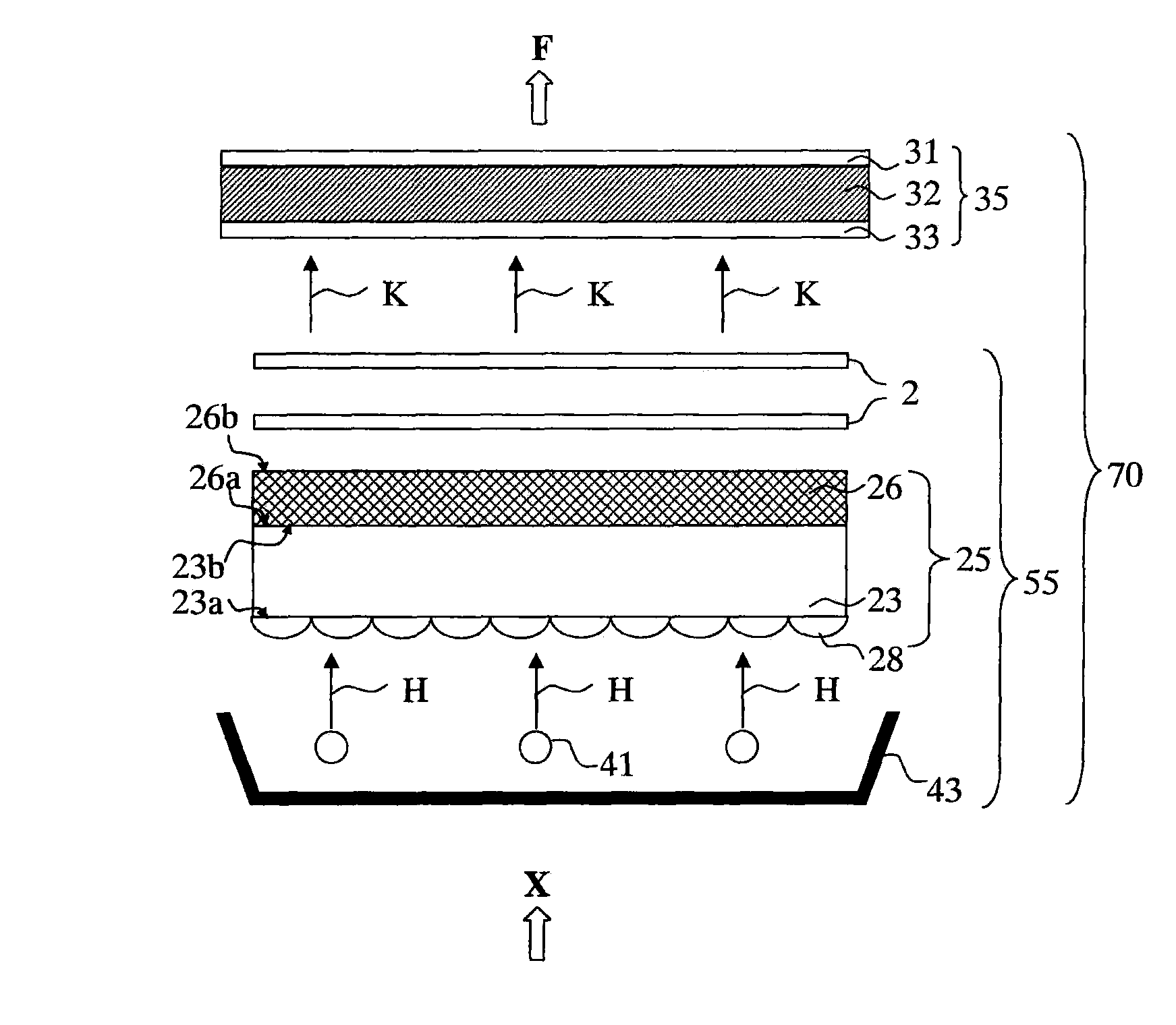
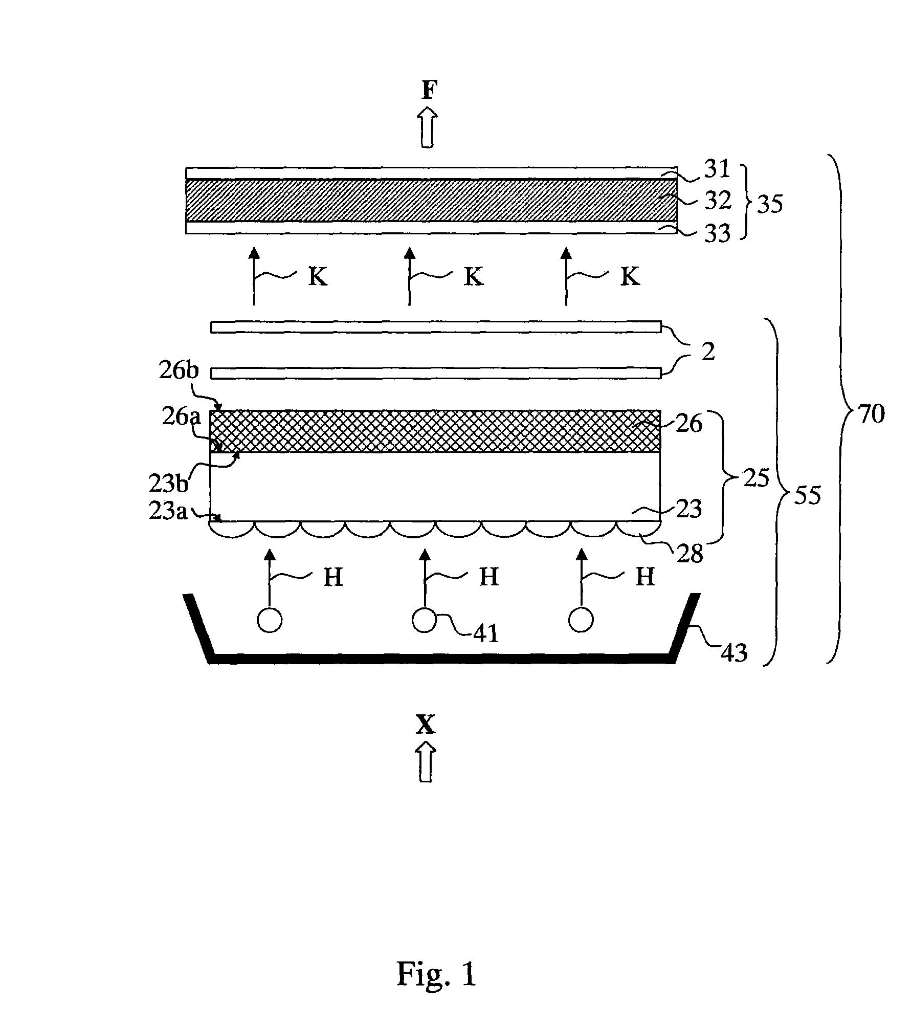
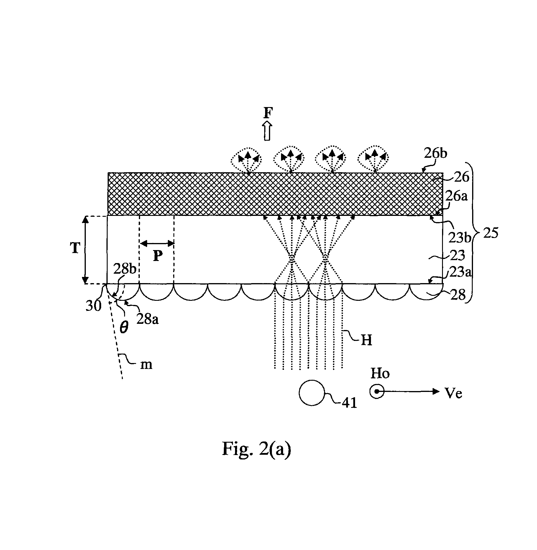
The present invention can provide an optical device, an optical uniform device, an optical sheet and a backlight unit and a display apparatus. In the present invention, a lamp image can be removed by uniformly emitting incident light from a plurality of light sources. Further, even if a distance between a light source and an optical device and between a light source and an optical uniform device are short, warpage due to heat generated from a light source does not occur.

Description

CROSS-REFERENCE TO RELATED APPLICATIONS[0001]This is a national stage entry of PCT Application No. PCT / JP2008 / 057547, filed Apr. 17, 2008, which is incorporated herein by reference in its entirety.TECHNICAL FIELD[0002]The present invention is related to an optical device, an optical uniform device, an optical sheet, a backlight unit and a display device, used for controlling a path of illuminating light. In particular, the present invention is related to an optical device, an optical uniform device, an optical sheet, a backlight unit and a display device, used for controlling a path of illuminating light in an image display device such as a flat panel display.BACKGROUND TECHNIQUE[0003]In a recent large scale liquid crystal display, a direct-lit type backlight has been adopted, wherein a plurality of Cold Cathode Fluorescent Lamp (CCFLs) or LEDs (Light Emitting Diode) are arranged. A diffusion plate having strong light scattering properties is used between an image display device and...

Claims


Application Information

Patent Timeline
Patent Type & Authority Patents(United States)
IPC IPC(8): G02F1/1335
CPCG02F1/133606G02F2001/133607G02F2201/54G02F1/133607
Inventor NAKAGOME, TOMOHIRO
Owner TOPPAN PRINTING CO LTD
Learn More