

Light-emitting element and light-emitting device employing the same
- Summary
- Abstract
- Description
- Claims
- Application Information
AI Technical Summary
Benefits of technology
Problems solved by technology
Method used
Image

Examples
embodiment mode 1
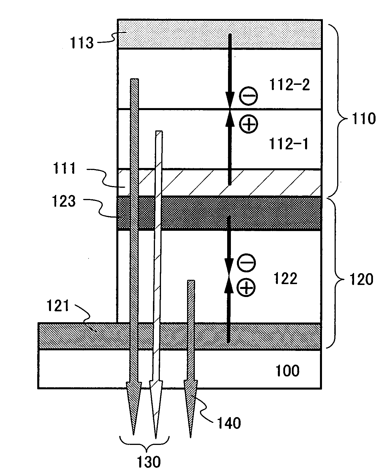
[0054]First, an example of a structure of stacked light-emitting elements will be described, with reference to FIG. 1A. A second light-emitting element 110 and a first light-emitting element 120 are stacked in series over a substrate 100. The first light-emitting element 120 has a structure which includes a first light-emitting layer 122 which is interposed between a first anode 121 and a first cathode 123.
[0055]Further, the second light-emitting element 110 has a structure which includes a second light-emitting layer 112-1 and a third light-emitting layer 112-2 which are interposed between a second anode 111 and a second cathode 113. The second light-emitting layer 112-1, the third light-emitting layer 112-2, and the first light-emitting layer 122 each include a light-emitting organic compound.
[0056]A light-emitting layer formed from a stack which includes the second light-emitting layer 112-1 and the third light-emitting layer 112-2 exhibits a light emission spectrum having two pe...
embodiment mode 2
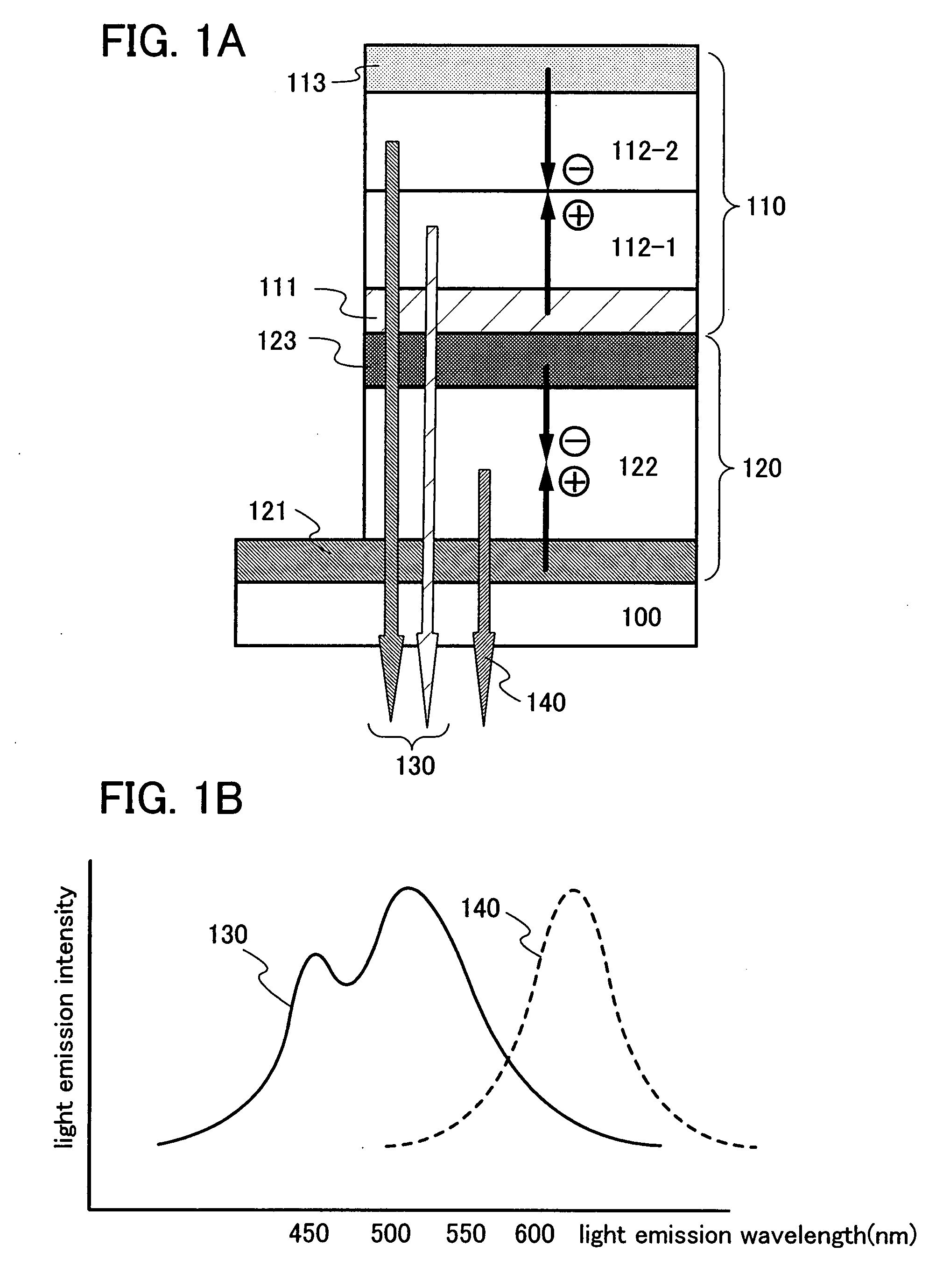
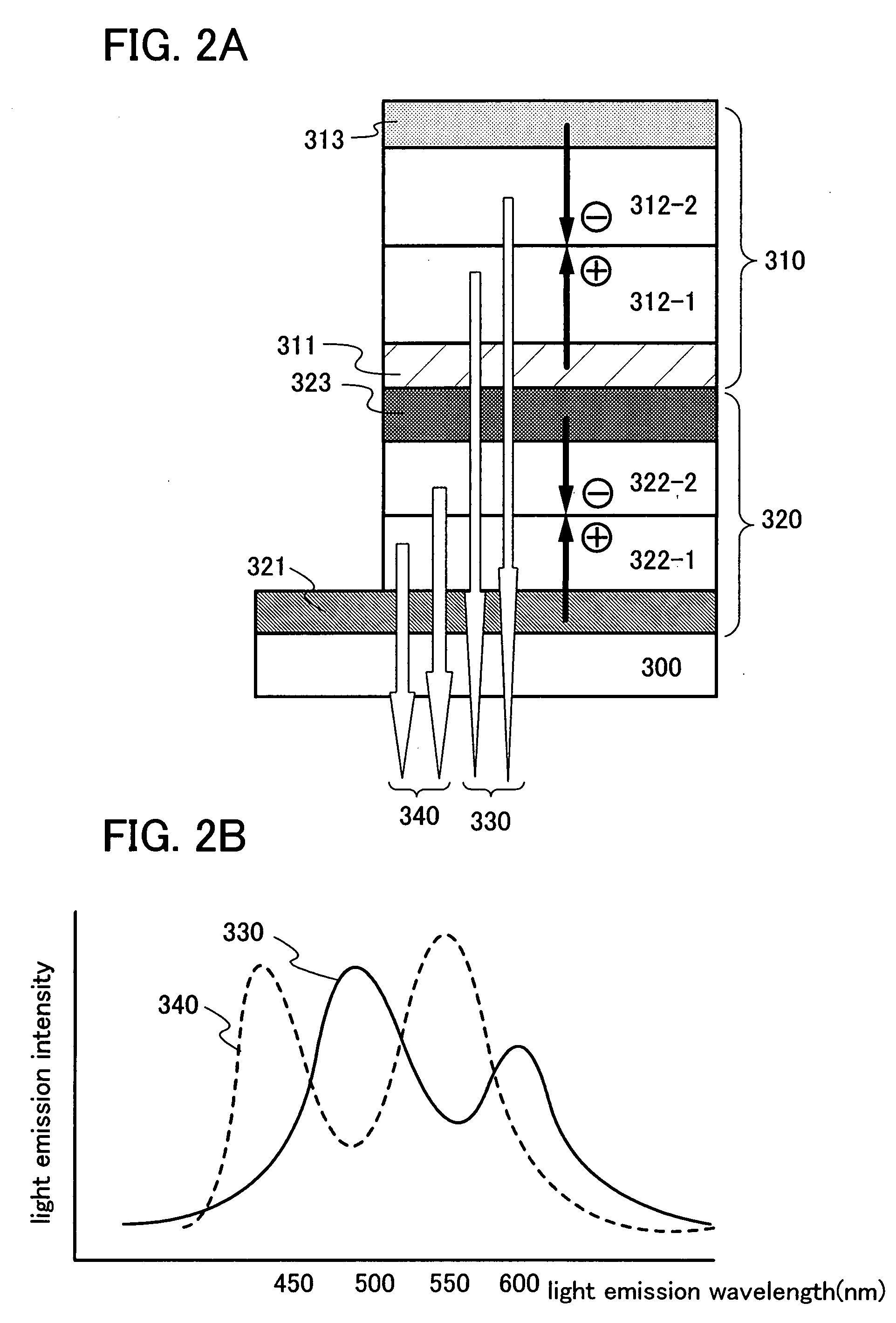
[0071]An element structure is shown in FIG. 2A. FIG. 2A is a structural example of a light-emitting element of the invention, in which a first light-emitting element 320 and a second light-emitting element 310 are stacked in series over a substrate 300. The first light-emitting element 320 has a structure which includes a first light-emitting layer 322-1 and a second light-emitting layer 322-2 which are interposed between a first anode 321 and a first cathode 323. Further, the second light-emitting element 310 has a structure which includes a third light-emitting layer 312-1 and a fourth light-emitting layer 312-2 which are interposed between a second anode 311 and a second cathode 313.
[0072]Here, a light-emitting layer of the first light-emitting element includes the first light-emitting layer 322-1 which exhibits a light emission spectrum having a peak in the orange to red wavelength range, and the second light-emitting layer 322-2 which exhibits a light emission spectrum having a...
embodiment mode 3
[0081]Below, materials and element structures which can be used for structures of light-emitting elements of the invention; that is, the first light-emitting element 120 and the second light-emitting element 110 in FIG. 1A, and the first light-emitting element 320 and the second light-emitting element 310 in FIG. 2A; will be described. In the structure in FIG. 1A, a hole injecting layer and / or a hole transporting layer may be provided between the second anode 111 and the second light-emitting layer 112-1 and between the first anode 121 and the first light-emitting layer 122. Further, in the structure in FIG. 1A, an electron injecting layer and / or an electron transporting layer may be provided between the second cathode 113 and the third light-emitting layer 112-2 and between the first cathode 123 and the first light-emitting layer 122. In the structure in FIG. 2A, a hole injecting layer and / or a hole transporting layer may be provided between the second anode 311 and the third light...
PUM
 Abstract
Description
Claims
Application Information