Protective device for high-voltage power equipment

A technology for high-voltage power equipment and fuse devices, applied in circuits, electrical switches, electrical components, etc., can solve the problems of burning transformers, fuses that cannot be used for power equipment, and accident expansion, so as to eliminate potential safety hazards and fill the field of overcurrent insurance. blank, realize the effect of overcurrent protection

Active Publication Date: 2014-01-08
何排枝
View PDF4 Cites 0 Cited by
  • Summary
  • Abstract
  • Description
  • Claims
  • Application Information

AI Technical Summary

Problems solved by technology

[0002] When the existing transformers and generators fail in the power supply line, the switch refuses to move, causing the transformers and generators to be damaged from time to time, especially the active high-voltage power equipment above 66kV, 110kV, 220kV, 330kV, and 500kV Due to the lack of safety devices suitable for this type of equipment, when the line current fails or is abnormal, the faulty current will damage this type of equipment, and in serious cases, it may burn the transformer and generator and cause a fire
However, the fuse in the prior art cannot be applied to power equipment above 35kV. This is because: in a circuit with a large fault current, when the fuse is blown at the moment, an arcing phenomenon will occur between the two electrodes, and the current Can not be cut off in time, resulting in damage to electrical equipment, and even further expand the accident

Method used


Image

  • Protective device for high-voltage power equipment
  • Protective device for high-voltage power equipment
  • Protective device for high-voltage power equipment

Examples


Embodiment Construction

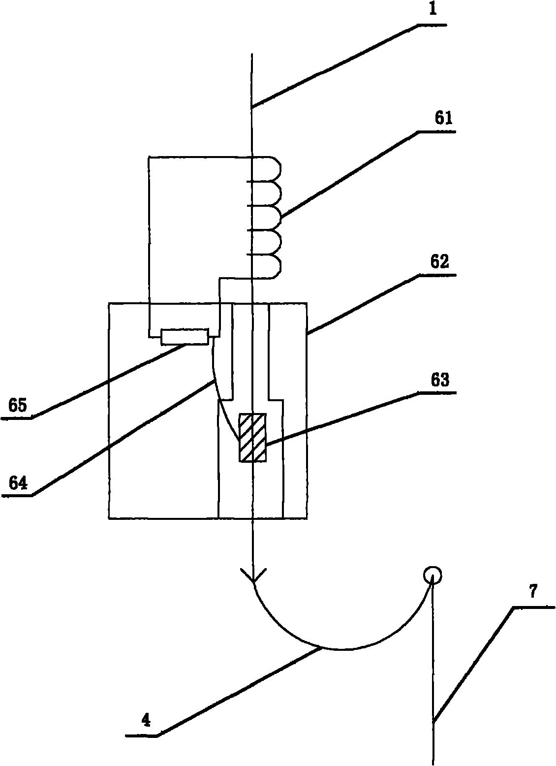
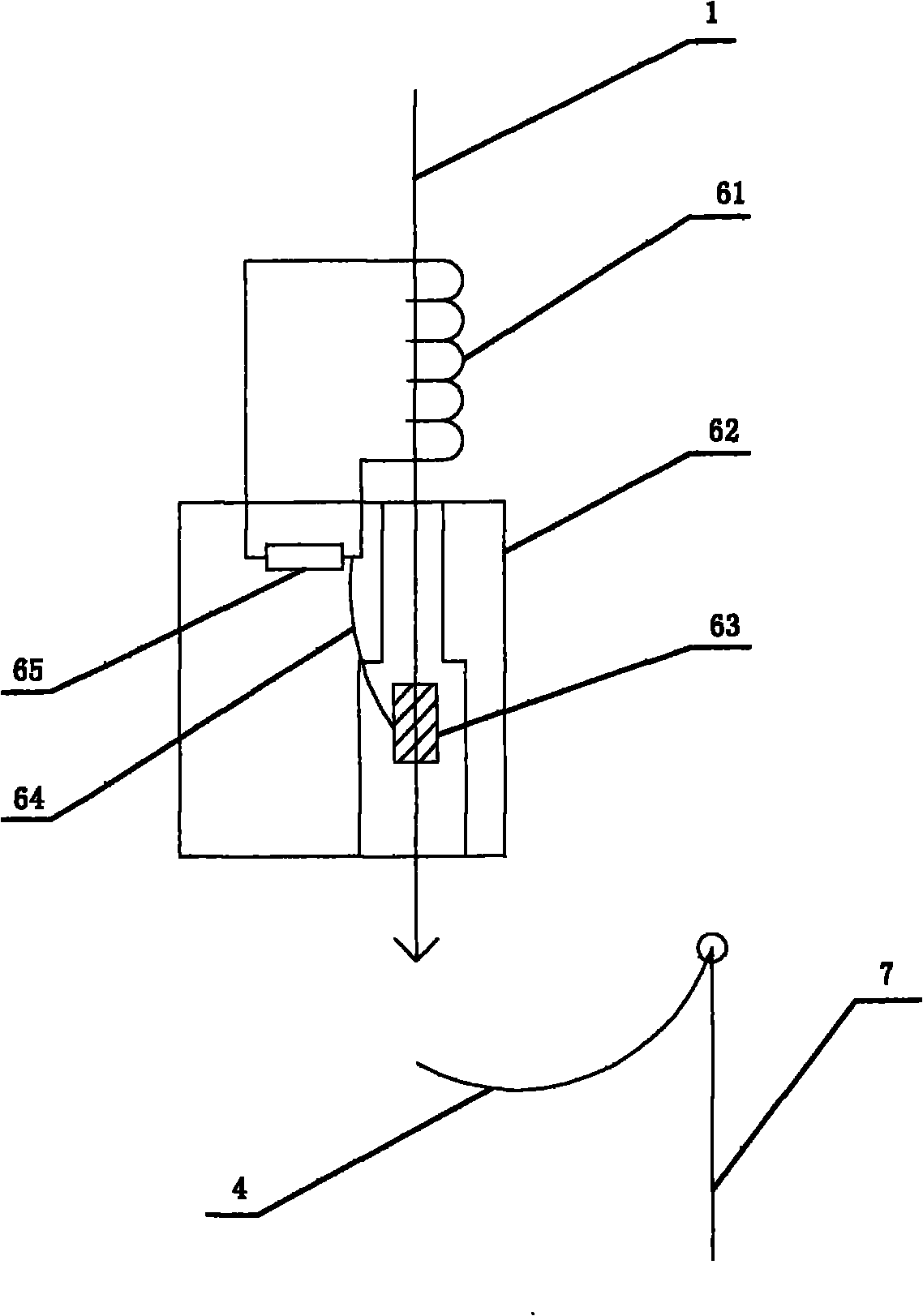
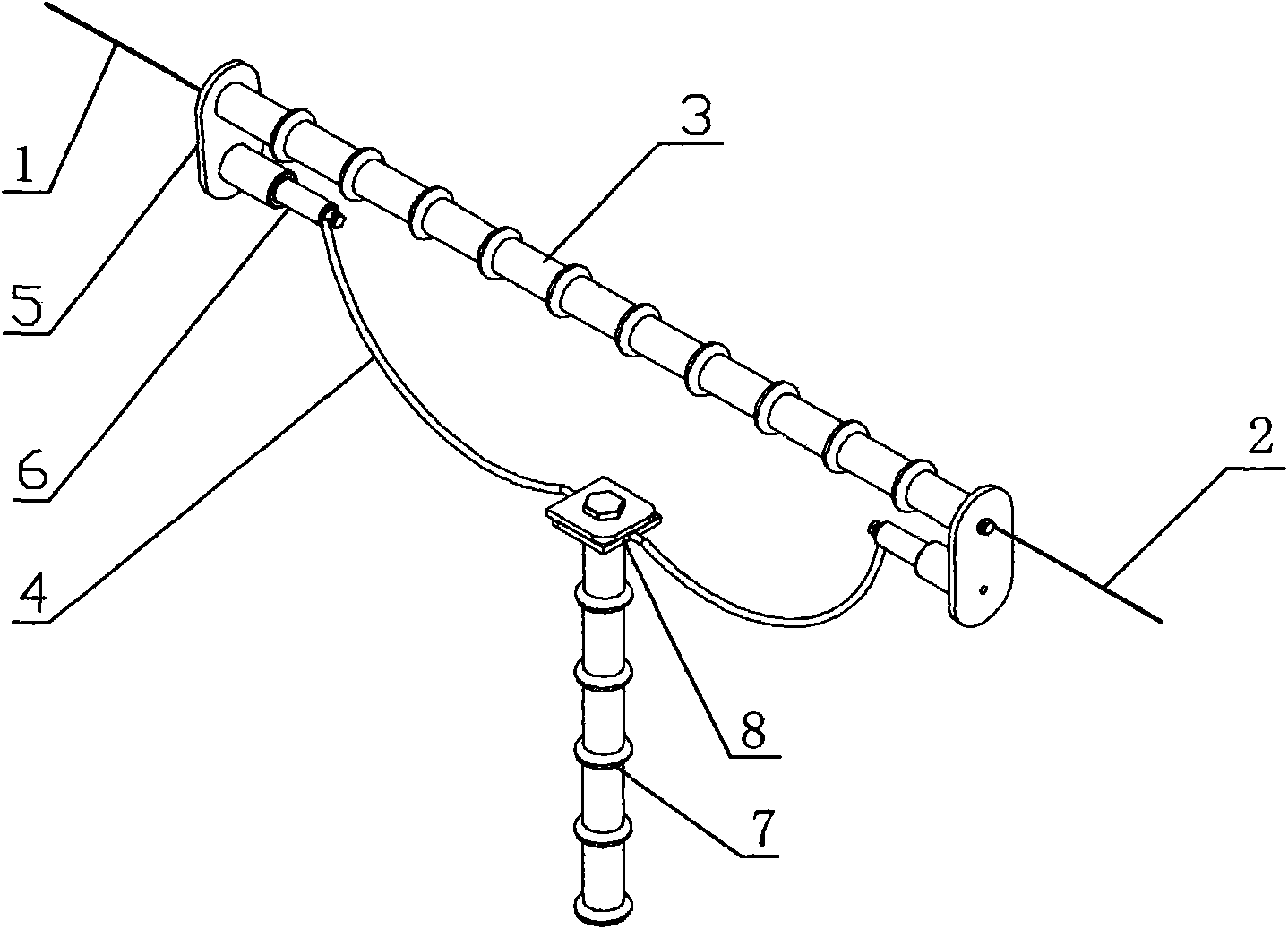
[0015] refer to figure 1 , figure 2 , a high-voltage power equipment safety device, including an insulating isolation bar 3 arranged between the left and right power supply busbars 1 and 2, a metal lead 4 is connected between the two ends of the insulating isolation bar 3, and the two ends of the insulating isolation bar At least one end of the part is provided with a disconnector 6 that can bounce off the metal lead wire under a fault current. One end of the disconnector 6 is connected to the insulating isolation bar 3 through the fixing device 5, and the other end is connected to the metal lead wire 4. The metal lead wire 4 The bottom is fixedly connected with an insulating support rod 7 to prevent the metal lead from bouncing off and grounding.

[0016] In order to ensure the safety of the electrical equipment, disconnectors 6 are provided at both ends of the isolating rod 3, so that even if the disconnector on one side breaks down, the disconnector on the other side can ...


PUM


Abstract

The invention discloses a protective device for high-voltage power equipment. The existing protective tubes for power equipment can not meet the requirement of the high-voltage power equipment for overcurrent protection, so the power equipment such as transformers, generators and the like is damaged from time to time. The protective device comprises an insulating spacer bar arranged between left and right power supply buses, wherein metal leads are connected between the two ends of the insulating spacer bar; at least one end of the two ends of the insulating spacer bar is provided with a disconnector which can flick the metal leads in the presence of fault current; one end of the disconnectors is connected with the insulating spacer bar via fixing devices and the other end of the disconnectors is connected with the metal leads; and an insulating support bar for preventing the metal leads from being flicked down and grounded is fixedly connected with the lower parts of the metal leads. The protective device has the following beneficial effects: the disconnectors are used for flicking the metal leads when the power supply circuits have fault current, and the leads droop under the actions of impact wave and gravity and break away from the circuits, thus achieving the aims of absolute arc extinction and fault stop, realizing overcurrent protection of the power equipment and filling in the gap in the field of overcurrent protection of the high-voltage power equipment.

Description

technical field [0001] The invention relates to a safety device for electric power equipment, in particular to a safety device for high-voltage power equipment such as transformers of 66kV, 110kV, 220kV, 330kV and 500kV, and can also be used as a safety device for high-power generators. Background technique [0002] When the existing transformers and generators fail in the power supply line, the switch refuses to move, causing the transformers and generators to be damaged from time to time, especially the active high-voltage power equipment above 66kV, 110kV, 220kV, 330kV, and 500kV However, due to the lack of safety devices suitable for this type of equipment, when the line current fails or is abnormal, the faulty current will damage this type of equipment. In severe cases, it may burn the transformer and generator and cause a fire. However, the fuse in the prior art cannot be applied to power equipment above 35kV. This is because: in a circuit with a large fault current, w...

Claims


Application Information

Patent Timeline
Patent Type & Authority Patents(China)
IPC IPC(8): H01H71/14H01H39/00
Inventor 何排枝
Owner 何排枝
Why Eureka
Try Eureka