Shoulder injecting device and related shoulder injecting method for hose upper part
What is Al technical title?
Al technical title is built by PatSnap Al team. It summarizes the technical point description of the patent document.
A hose and shoulder injection technology, applied in the field of hose, can solve the problems of low efficiency and slow speed, and achieve the effect of high efficiency, fast shoulder injection speed and simple structure
Active Publication Date: 2014-06-04
三樱包装(江苏)有限公司
View PDF4 Cites 0 Cited by
Summary
Abstract
Description
Claims
Application Information
AI Technical Summary
This helps you quickly interpret patents by identifying the three key elements:
Problems solved by technology
Method used
Benefits of technology
Problems solved by technology
This kind of shoulder injection method is not a wheel-disc rotary shoulder injection method. Usually, two sets of mandrels operate alternately and a set of molding mechanism cooperates to inject shoulders. Each set of mandrels is about 8 pieces, and the machine speed is about 20 pieces / min. 3 to 4 operators are required, the speed is slow and the efficiency is low
Method used
Image
Click on the blue label to locate the original text in one second.
Reading with bidirectional positioning of images and text.
Examples
Embodiment Construction
[0028] In order to understand the technical content of the present invention more clearly, the following examples are given in detail, the purpose of which is only to better understand the content of the present invention but not to limit the protection scope of the present invention.
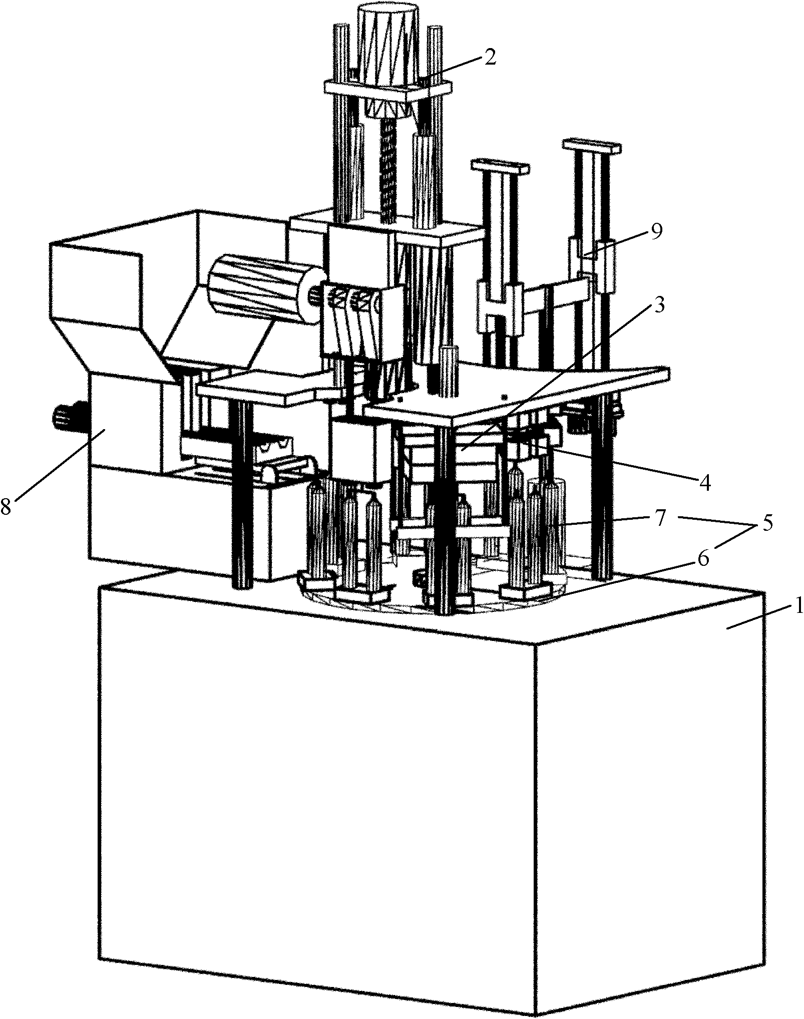
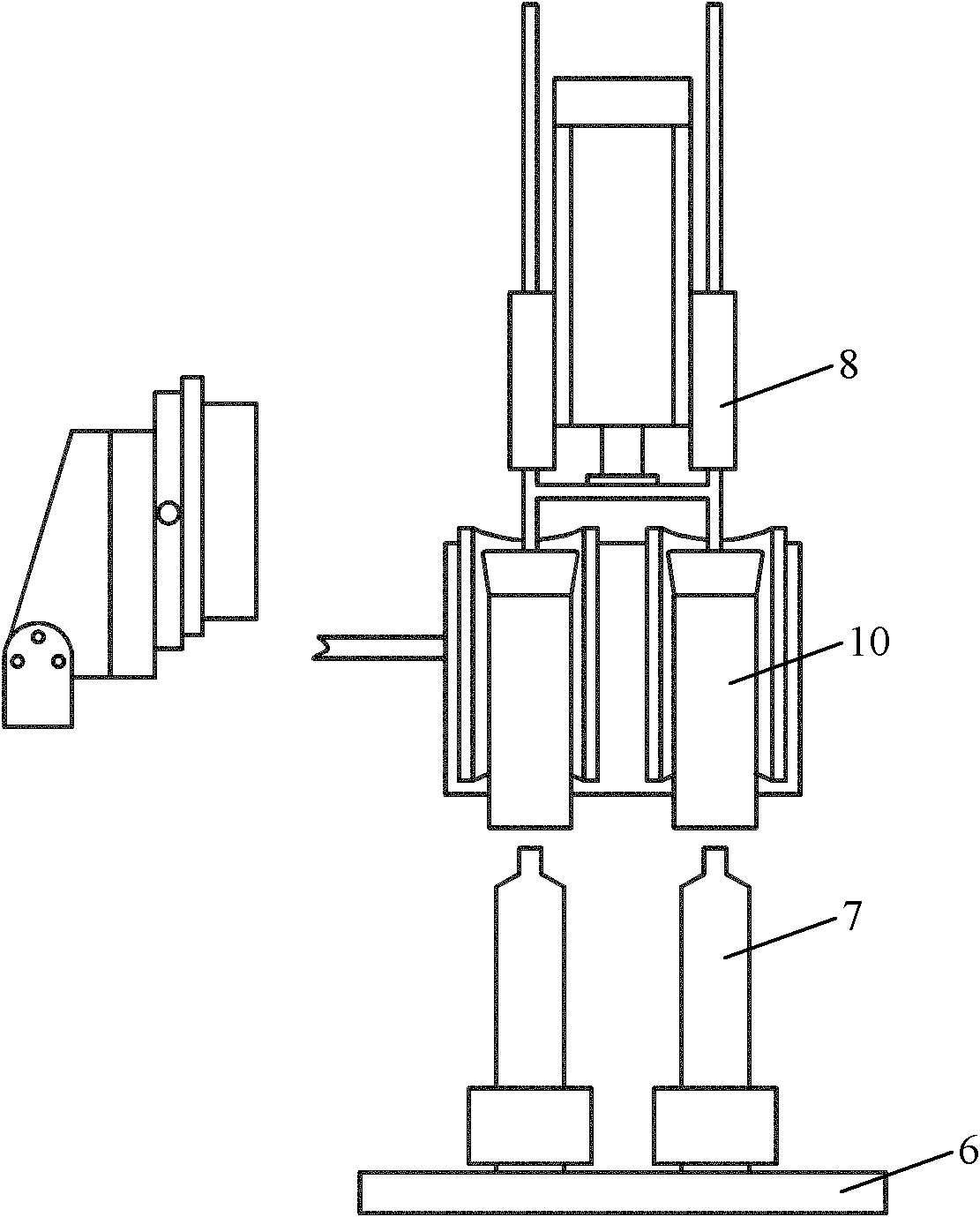
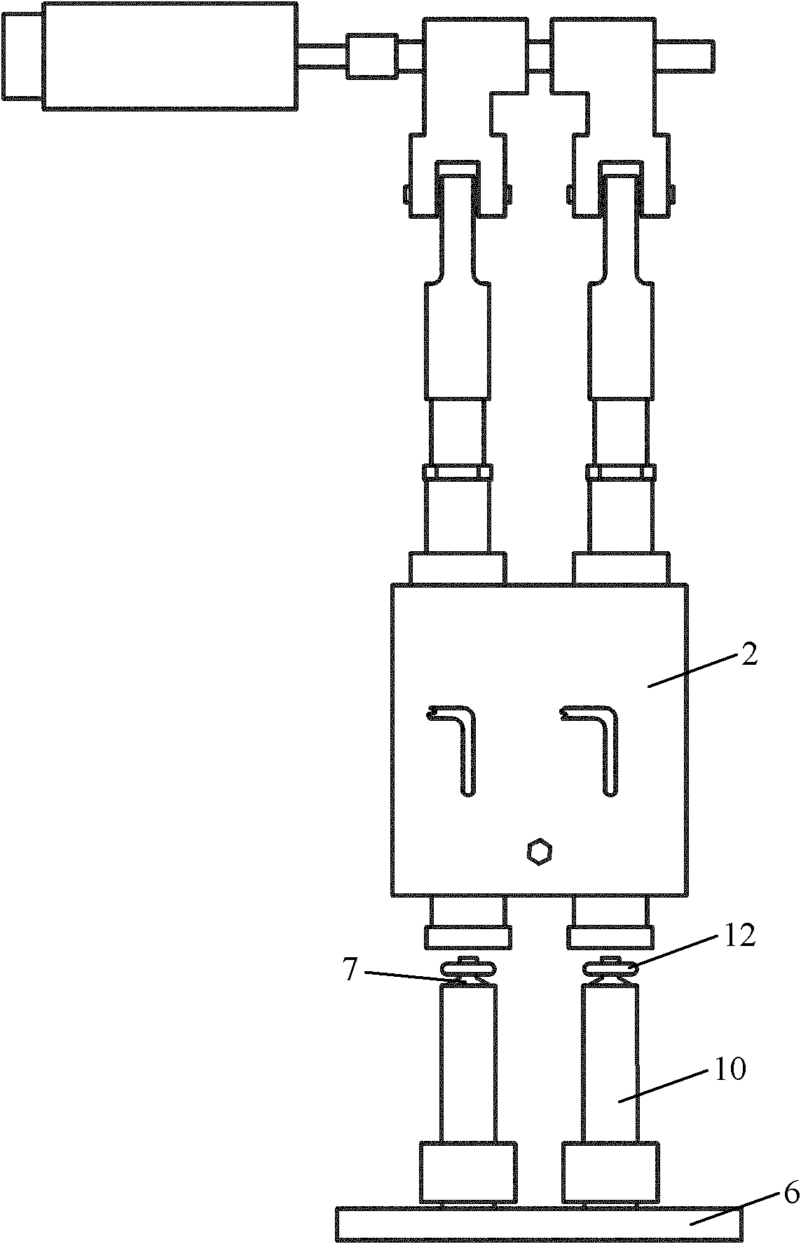
[0029] See Figure 1-7 As shown, the hose upper shoulder injection device of the present invention includes a control mechanism (not shown), a frame 1 and an injection molding mechanism 2 arranged on the frame 1, a tube shoulder molding mechanism 3, and a cooling molding mechanism 4. Turntable assembly 5 and driving parts (not shown), said turntable assembly 5 includes a turntable 6 and a number of mandrels 7, said mandrel 7 is arranged on said turntable 6 and is formed with respect to the center of said turntable 6 Arranged in a circle, the driving parts are connected to the turntable 6 to drive the turntable 6 to rotate, the injection molding mechanism 2, the shoulder molding mechanism 3 and ...
PUM
Abstract
The invention relates to a shoulder injecting device for a hose upper part, comprising a controlling mechanism, a stand, an injection molding and discharging mechanism, a hose shoulder compression molding mechanism, a cooling molding mechanism, a turntable assembly and a driving part, wherein the injection molding and discharging mechanism, the hose shoulder compression molding mechanism, the cooling molding mechanism, the turntable assembly and the driving part are arranged on the stand, the turntable assembly comprises a turntable and a plurality of core rods, the core rods are arranged on the turntable and circularly arrayed relative to the center of the turntable, the driving part is connected with the turntable and used for driving the turntable to rotate, the injection molding and discharging mechanism, the hose shoulder compression molding mechanism and the cooling molding mechanism are arrayed to form a circle and respectively located above different core rods, the controlling mechanism is respectively and electrically connected with the injection molding and discharging mechanism, the hose shoulder compression molding mechanism, the cooling molding mechanism and the driving part, and preferably, the shoulder injecting device further comprises an automatic hose feeding mechanism and an automatic hose detaching mechanism. The invention further provides a related shoulder injecting method for the hose upper part. The shoulder injecting device for the hose upper part, provided by the invention, is skillful in design and concise in structure, has the advantages of high speed and high efficiency when used for shoulder injecting, and is suitable for large-scale popularization and application.
Description
technical field [0001] The invention relates to the technical field of hoses, in particular to the technical field of hose manufacturing, in particular to a hose upper shoulder injection device and a related hose upper shoulder injection method. Background technique [0002] The commonly used way of injecting the upper part of the hose is to put the hose on the mandrel, press down the mold bowl platen, close the mold with the mandrel, and then the injection molding mechanism spits out the material, which is completed under the action of the molding mechanism and the cooling mechanism. Note the shoulder, which belongs to the mold bowl and the mandrel are first clamped, and then the material is discharged. This kind of shoulder injection method is not a wheel-disc rotary shoulder injection method. Usually, two sets of mandrels operate alternately and a set of molding mechanism cooperates to inject shoulders. Each set of mandrels is about 8 pieces, and the machine speed is abou...
Claims
Application Information
Patent Timeline
Application Date:The date an application was filed.
Publication Date:The date a patent or application was officially published.
First Publication Date:The earliest publication date of a patent with the same application number.
Issue Date:Publication date of the patent grant document.
PCT Entry Date:The Entry date of PCT National Phase.
Estimated Expiry Date:The statutory expiry date of a patent right according to the Patent Law, and it is the longest term of protection that the patent right can achieve without the termination of the patent right due to other reasons(Term extension factor has been taken into account ).
Invalid Date:Actual expiry date is based on effective date or publication date of legal transaction data of invalid patent.