Linear actuator

A technology of linear actuation device and sliding table, applied in the direction of fluid pressure actuation device, etc., can solve the problems of skew, sliding table tilt, displacement and so on

Active Publication Date: 2011-07-06
SMC CORP
View PDF7 Cites 10 Cited by
  • Summary
  • Abstract
  • Description
  • Claims
  • Application Information

AI Technical Summary

Problems solved by technology

[0004] However, with the conventional technology disclosed in the aforementioned Japanese Patent Laid-Open No. 2008-057679, for example, when the slide table is displaced under the condition that

Method used


Image

  • Linear actuator
  • Linear actuator
  • Linear actuator

Examples


Embodiment Construction

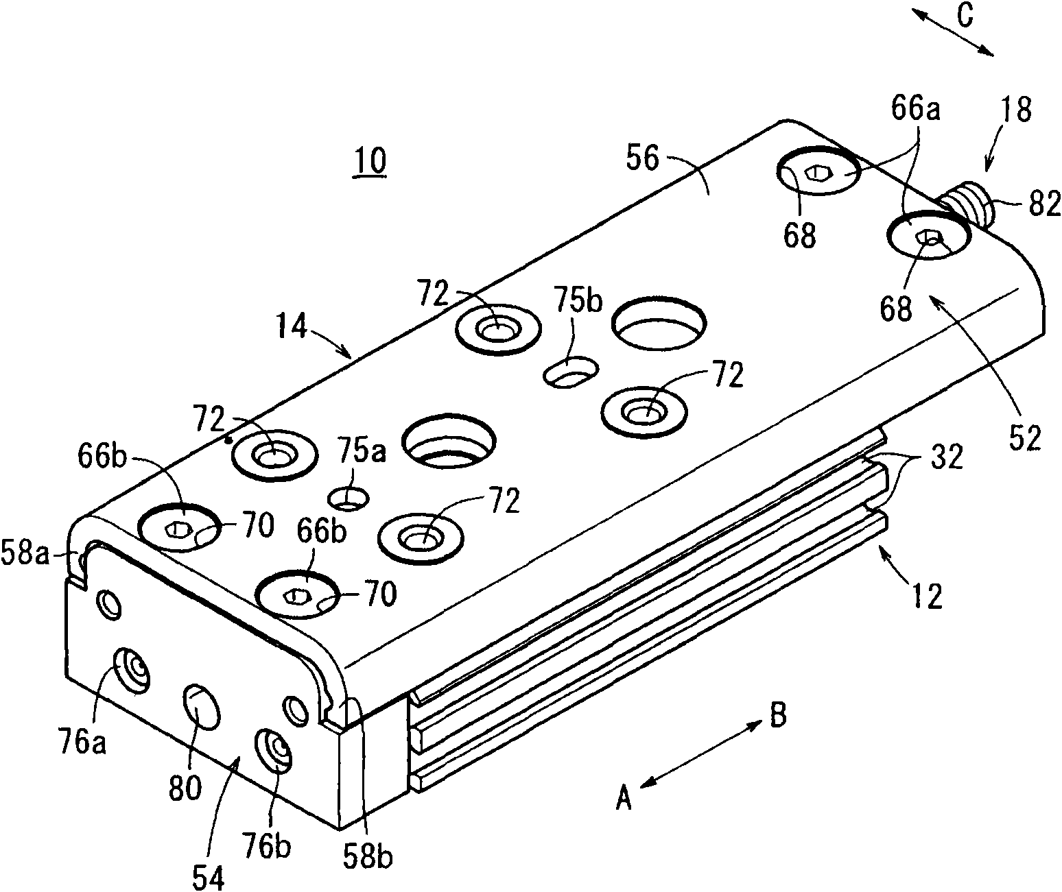
[0037] exist figure 1 , reference numeral 10 designates a linear actuator according to a first embodiment of the present invention.

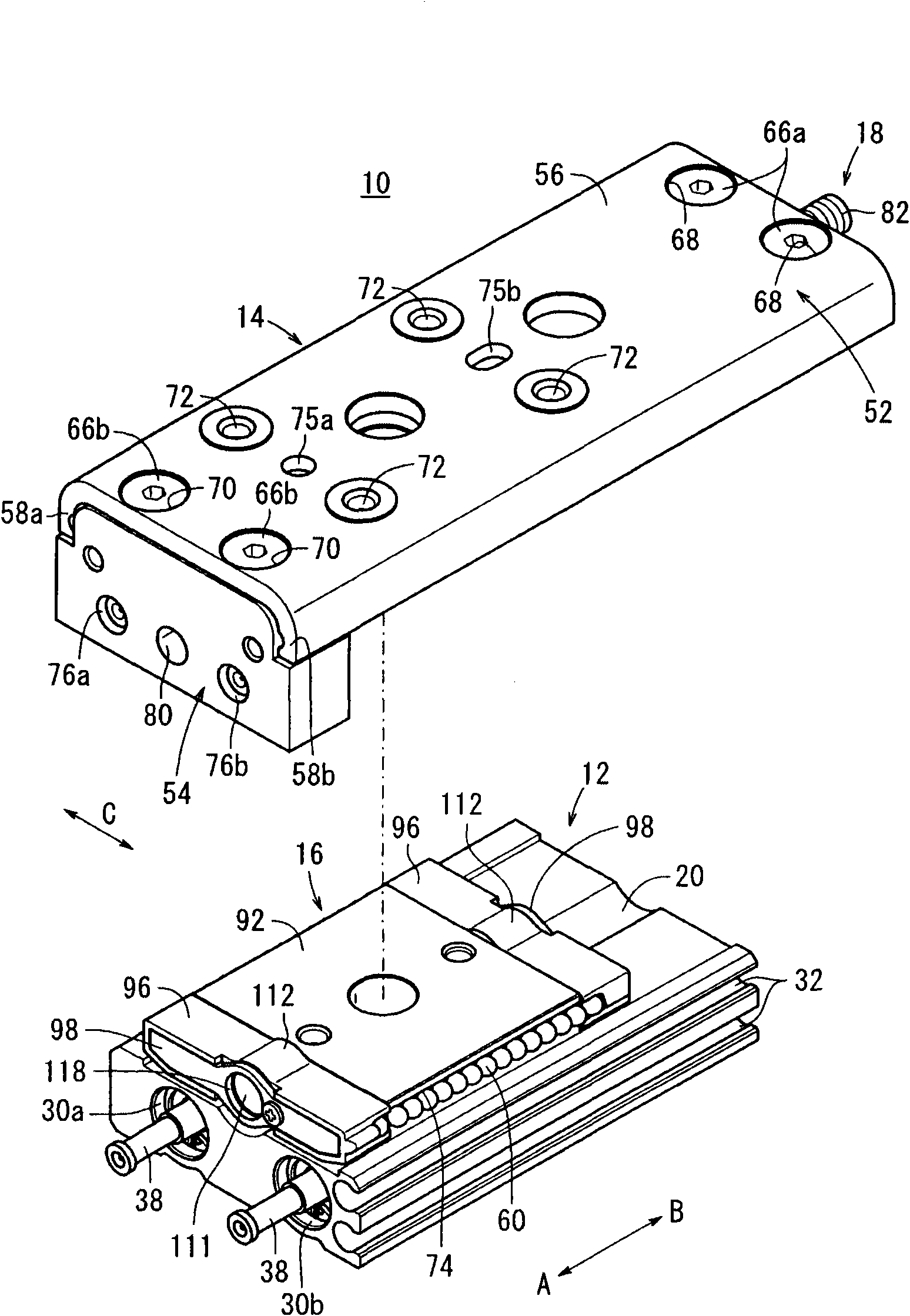
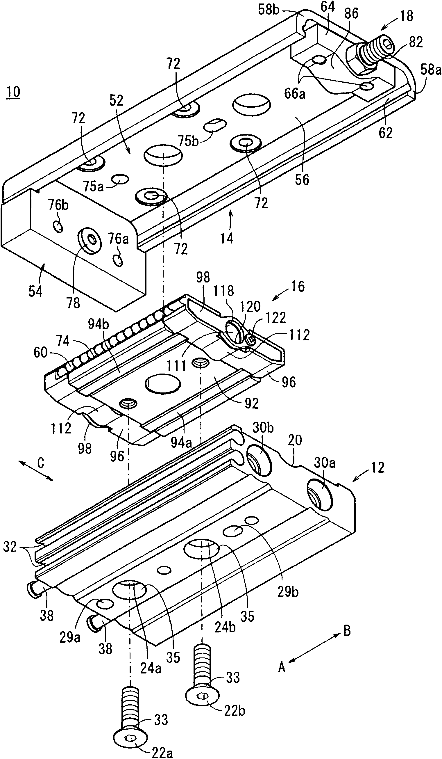
[0038] Such as Figures 1 to 10 As shown, the linear actuator 10 includes a cylinder 12 , a slide table 14 , a guide mechanism 16 , and a stopper mechanism 18 . Wherein, the slide table 14 is positioned at the top of the cylinder block 12, and reciprocates along a straight line in the longitudinal direction (directions shown by arrows A and B); the position of the guide mechanism 16 is between the cylinder block 12 and the slide table 14, and The slide table 14 is guided in the longitudinal direction (directions indicated by arrows A and B); the stopper mechanism 18 can adjust the displacement of the slide table 14 .

[0039] The cylinder 12 has a rectangular cross-section, and has a predetermined length in a length direction (directions indicated by arrows A and B). A depression 20 having a depressed arcuate cross-section is formed approxima...


PUM


Abstract

A linear actuator (10) includes a cylinder main body (12). With respect to the cylinder main body (12), a slide table (14) is disposed for reciprocal displacement through a guide mechanism (16), which is disposed on the cylinder main body. A stopper mechanism (18) having a stopper bolt (82) is disposed on one end of the slide table (14) centrally in a widthwise direction perpendicular to the longitudinal direction of the slide table (14). In addition, when the slide table (14) is displaced along the cylinder main body (12), one end of the stopper bolt (82) comes into abutment with an end of a cover (96) of the guide mechanism (16), whereupon the slide table (14) becomes engaged therewith and movement of the slide table (14) is stopped.

Description

technical field [0001] The invention relates to a linear actuating device, which can make a slide table reciprocate along the axial direction of a cylinder body by introducing pressure fluid from a fluid inlet / outlet. Background technique [0002] Hitherto, a linear actuator made of, for example, a fluid pressure cylinder or the like has been employed as a means for transferring a workpiece. In Japanese Utility Model No. 2586276, the applicant proposed a linear actuator device, which can transport the Workpiece on slide table. [0003] Further, in Japanese Patent Laid-Open No. 2008-057679, a linear actuator equipped with a non-circulating guide mechanism is disclosed, wherein a plurality of steel balls are arranged in the main body between the guide rail and the slide table, thereby The steel balls are displaced following the displacement of the slide table. [0004] However, with the conventional technology as disclosed in the aforementioned Japanese Patent Laid-Open No....

Claims


Application Information

Patent Timeline
IPC IPC(8): F15B15/02F15B15/14
CPCF15B15/24
Inventor 石桥康一郎高梨精二佐藤太平政所二朗原耕二佐藤俊夫
Owner SMC CORP
Why Eureka
Try Eureka