Dual-output atomizer

An atomizer and outlet end technology, which is applied in the field of dual-output atomizers, can solve the problems of inability to continue, unable to provide energy supply, etc., and achieve the effect of good combustion efficiency

Active Publication Date: 2012-06-27
西斐(上海)工业控制有限公司
View PDF0 Cites 1 Cited by
  • Summary
  • Abstract
  • Description
  • Claims
  • Application Information

AI Technical Summary

Problems solved by technology

In a program-controlled control environment, if the burner cannot be put into operation correctly or any one of the programs (actions) fails, the next program will not be able to proceed
In this way, even if the burner is put into operation in time, it cannot provide timely energy supply.

Method used


Image

  • Dual-output atomizer
  • Dual-output atomizer
  • Dual-output atomizer

Examples


Embodiment Construction

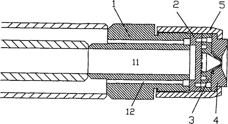
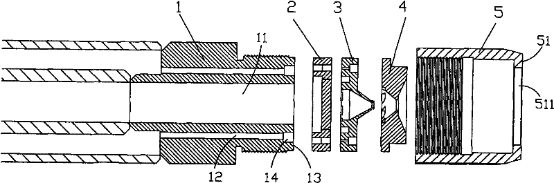
[0029] see Figure 1 ~ Figure 5c , the dual-output atomizer of the present invention, which includes a body 1, a splitter 2, an atomizer A3, an atomizer B4, and an end cap 5;

[0030] The body 1 is in the form of a cylinder, with a channel A11 in the center, and a channel B12 on the outside of the central channel A11; the end surface 13 at the outlet end of the body channel B12 is provided with an annular groove 14, and the outlet end of the channel B12 is located in the ring. Groove 14 bottom.

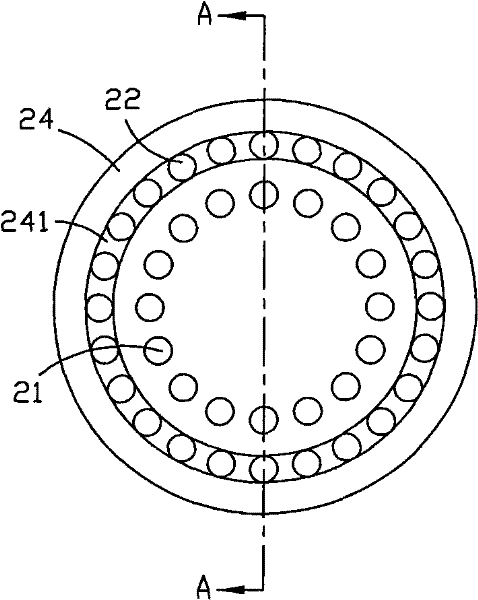
[0031] The splitter 2, one side of which is against the body 1, corresponds to the central channel A11 and the channel B12 of the body, and the splitter 2 is provided with two inner and outer circles of through holes along the circumference, forming the first oil inlet hole 21 and the second oil inlet hole 22 ;

[0032] Atomizer A3, one side of which is against the splitter plate 2, the side 31 is provided with an annular oil equalizing groove 311, and the center of the annular oil ...


PUM


Abstract

The invention relates to a dual-output atomizer, which comprises a body, a splitter vane, an atomizer A and an atomizer B, wherein the splitter vane, the atomizer A and the atomizer B are sequentially propped against the body and are sheathed and fixed by an end cover; the body is cylindrical, and a channel A and a channel B are formed at the center; one side of the splitter vane is propped against the body, for corresponding to the channel A and the channel B of the body, an inner circle of through holes and an outer circle of through holes are formed on the splitter vane; an annular oil balancing groove and a spin chamber, as well as a tangential groove around the spin chamber are formed on the side surface of the atomizer A, which is propped against the splitter vane; third oil inlet holes are arranged on the outer side of the annular oil balancing groove along the circumference of the atomizer A; a spin chamber corresponding to the spin chamber of the atomizer A is arranged on theside surface of the atomizer B, which is propped against the atomizer A, and the tangential groove is further arranged around the spin chambers; and a horn-shaped spout, which is communicated with the spin chamber and inwards concave, is arranged on the other side surface of the atomizer B. The two atomizers using a same set of program and mechanism used for controlling advance and retreat can simultaneously perform advance and retreat, and a variety of energy can be accurately and timely supplied under complex and emergency working conditions, thereby meeting complex combustion requirements of energy supply under the different working conditions.

Description

technical field [0001] The invention relates to burner technology, in particular to a dual-output atomizer suitable for boilers using fuel burners in power stations, petrochemicals, and metallurgy. By controlling different fuel flow rates, it can satisfy different fuel flow supply under various load stages. Background technique [0002] Oil burners used in oil-fired boilers in industries such as power stations, petrochemicals, and metallurgy have always been traditional, single-output atomizers. In each stage of boiler operation, in different load segments, different energy supplies are required. Generally, the required energy can be achieved by the following two methods: [0003] 1. Replace the atomizer of the burner to achieve the required energy supply; [0004] 2. Increase or decrease the number of burners in operation to achieve the required energy supply. [0005] Both methods have certain disadvantages: [0006] 1. To replace the atomizer, the burner must be shut ...

Claims


Application Information

Patent Timeline
Patent Type & Authority Patents(China)
IPC IPC(8): F23D11/44
Inventor 马明叶正桂黄志高
Owner 西斐(上海)工业控制有限公司
Why Eureka
Try Eureka