Spraying type environmentally-friendly electronic powder painting mechanism

An electronic powder, environmentally friendly technology, applied in the manufacture of circuits, electrical components, electrode systems, etc., can solve the problems affecting the uniformity of electronic powder, the decline of product stability, and increase the cost of production enterprises, so as to save cooling and heat preservation costs. , Low operating cost, and the effect of improving uniformity

Inactive Publication Date: 2013-03-20
漳州市德晟电光源设备有限公司
View PDF2 Cites 0 Cited by
  • Summary
  • Abstract
  • Description
  • Claims
  • Application Information

AI Technical Summary

Problems solved by technology

[0002] At present, domestic electronic powder is generally packed in ordinary cups. In order to reduce the precipitation of electronic powder, the prepared electronic powder is placed in a general open cup and placed on a vibrator for vibration. In general, the electronic powder cup has a large opening. The electronic powder solution (butyl acetate) has a large amount of volatilization, which leads to uneven concentration of the electronic powder. At the same time, the entire electronic powder cup is constantly vibrating. The friction between the electronic powder and the container and the electronic powder produces certain charged particles, which makes the electronic powder form a group. Flocculation, which further affects the uniformity of electronic powder
At the same time, because butyl acetate is relatively volatile and has certain toxicity, the thread stretching work is required to be carried out in an air-conditioned room with a relatively low temperature. Poor exhaust not only increases the cost of the production enterprise, but also causes pollution to the working environment of the workers.
In summary, this common production process makes the product less stable and increases the production cost of the enterprise

Method used


Image

  • Spraying type environmentally-friendly electronic powder painting mechanism
  • Spraying type environmentally-friendly electronic powder painting mechanism
  • Spraying type environmentally-friendly electronic powder painting mechanism

Examples


Embodiment Construction

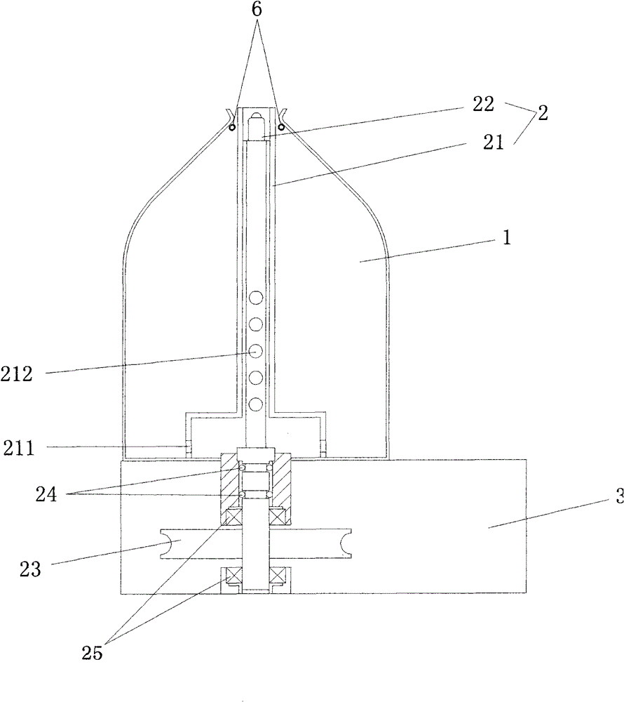
[0034] Such as figure 1 Shown is a suction spray type environmental protection type electronic powder mechanism, which includes a container 1, a suction spray device 2 and a base 3 for placing the container 1, and the suction spray device 2 includes a feeding part and a driving part; the feeding part passes through Some bearings 25 are rotatably fixed on the base 3 and stretch into the container 1; the drive unit is located in the base 3, and it includes: a transmission wheel 23, a motor driving the transmission wheel 23; Airtightness, the feeding part is provided with a sealing ring 24 from the position of the transmission wheel 23 and the connection between the container 1 and the base 3 .

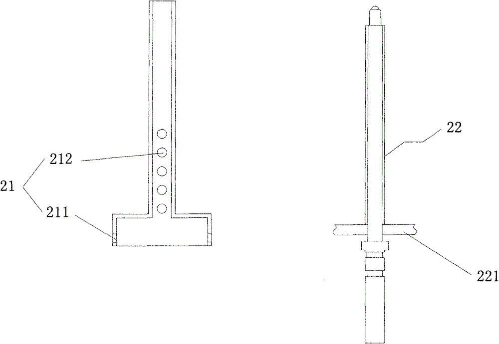
[0035] Such as figure 2 As shown: the feeding part includes: an inverted T-shaped pipe 21 and a feeding pipe 22; the horizontal part of the inverted T-shaped pipe 21 is provided with an opening 211, and the middle part is provided with a suction and overflow hole 212 (hereinafter refer...


PUM


Abstract

The invention provides a spraying type environmentally-friendly electronic powder painting mechanism. The mechanism is provided with a container for holding electronic powder suspension, wherein a spraying device is arranged in the container; a liquid inlet of the spraying device is arranged at the bottom of the container, and the position of a liquid outlet and power of the spraying device can achieve the following effects: the electronic powder suspension can stably overflow or be sprayed from the liquid outlet, and the peak of the overflowed or sprayed suspension can achieve a certain set position higher than the surface of the suspension. As long as a core column with hung filament reaches the set position, the core column can directly contact the electronic powder. Compared with the traditional mechanical structure which moves the electronic powder up and down, the spraying type environmentally friendly electronic powder painting mechanism has a more stable and compact effect, and can ensure that the stability of the product cannot be influenced.

Description

technical field [0001] The invention mainly relates to a mechanism for applying electronic powder to a core column in the production process of the electric light source industry, in particular to an electronic powder applying mechanism equipped on a wire stretching machine. Background technique [0002] At present, domestic electronic powder is generally packed in ordinary cups. In order to reduce the precipitation of electronic powder, the prepared electronic powder is placed in a general open cup and placed on a vibrator for vibration. In general, the electronic powder cup has a large opening. The electronic powder solution (butyl acetate) has a large amount of volatilization, which leads to uneven concentration of the electronic powder. At the same time, the entire electronic powder cup is constantly vibrating. The friction between the electronic powder and the container and the electronic powder produces certain charged particles, which makes the electronic powder form a...

Claims


Application Information

Patent Timeline
Patent Type & Authority Patents(China)
IPC IPC(8): H01J9/02
Inventor 祝增水
Owner 漳州市德晟电光源设备有限公司
Why Eureka
Try Eureka