Humidifying apparatus
A technology of humidifying device and supplying device, applied in air humidification system, heating method, lighting and heating equipment, etc., can solve the problems of high water leakage and splashing, and achieve the effect of preventing water splashing
- Summary
- Abstract
- Description
- Claims
- Application Information
AI Technical Summary
Problems solved by technology
Method used
Image

Examples
no. 1 approach
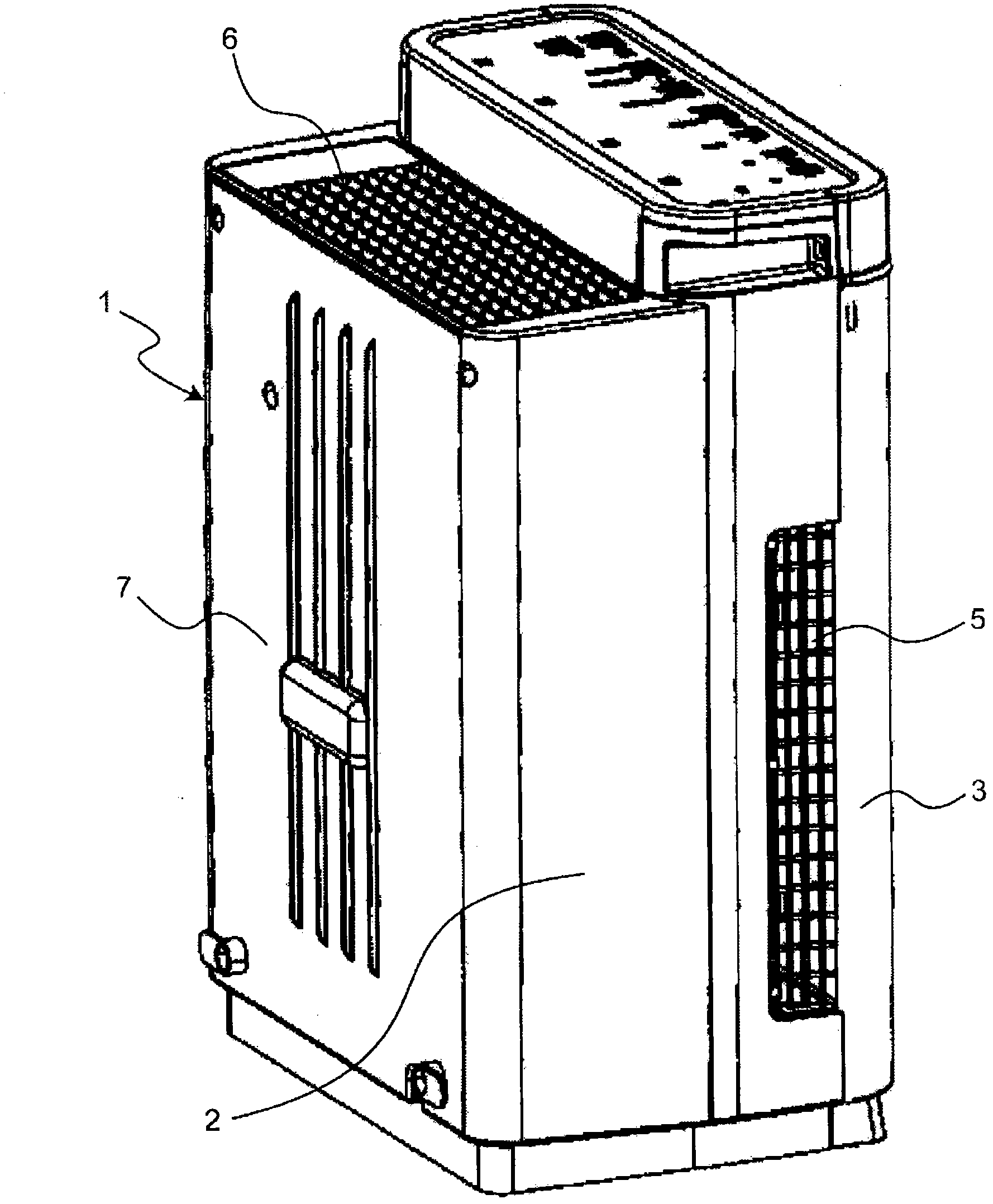
[0069] figure 1 The perspective view which shows 1st Embodiment of the humidifier of this invention. Such as figure 1 As shown, the humidifier includes a housing 1, which is composed of a housing main body 2 and a front panel 3 detachably mounted on the housing main body 2.
[0070] Suction ports 5, 5 are provided on both sides of the housing 1 (refer to image 3 ), an air outlet 6 is provided at the rear portion of the upper surface of the casing 1.
[0071] In this way, in this humidifier, the suction ports 5 and 5 are provided on the side surfaces of the casing 1, the blowing outlet 6 is provided on the upper surface of the casing 1, and the rear surface 7 of the casing 1 does not have the suction port and the blowing port. Therefore, the rear surface 7 of the casing 1 of the humidifier can be in close contact with the wall surface of the room (not shown), and the degree of freedom of installation of the humidifier is high.
[0072] In conventional humidifiers, the suct...
no. 2 approach
[0196] Figure 27 A perspective view showing an air conditioner using a humidifier according to a second embodiment of the present invention.
[0197] Such as Figure 27 As shown, in this air conditioner, a fan 302 , a dehumidification unit 303 , a humidification unit 304 as an example of a humidification device, an air cleaning unit 305 , and a control unit 300 are accommodated in a casing 301 .
[0198] The fan 302 is located on the opposite side of the air purifier 305 relative to the housing 301 , and the air purifier 305 , the dehumidifier 303 , the humidifier 304 , and the fan 302 are arranged sequentially from the air purifier 305 side. When the fan 302 works, air is sucked in from the suction ports 305a, 305b, and 305c on the side of the air purifier 305, and forms an air path A that passes through the dehumidification unit 303 and then passes through the humidification unit 304 to reach the fan 302. Air from the fan 302 is blown out from an outlet 301c provided on t...
PUM
 Abstract
Description
Claims
Application Information