Contact riveter

A riveting machine and contact technology, which is applied in metal processing equipment, feeding devices, positioning devices, etc., can solve the problems of long operation time, unsafe, and rising operating costs of parts, and achieves improved working environment, high efficiency, Good assembly quality

Inactive Publication Date: 2011-07-13
周俊雄
View PDF5 Cites 22 Cited by
  • Summary
  • Abstract
  • Description
  • Claims
  • Application Information

AI Technical Summary

Problems solved by technology

Among them, the positioning and alignment of the contact point and the prefabricated hole on the coil material is a major difficulty during the operation process. Although there is a mold to guide it, it still relies on manual auxiliary correction, and the size of the contact point is small, which brings great diff

Method used


Image

  • Contact riveter
  • Contact riveter
  • Contact riveter

Examples


Embodiment Construction

[0030] The present invention will be further described below in conjunction with specific examples, but the specific examples do not limit the present invention in any way.

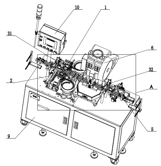
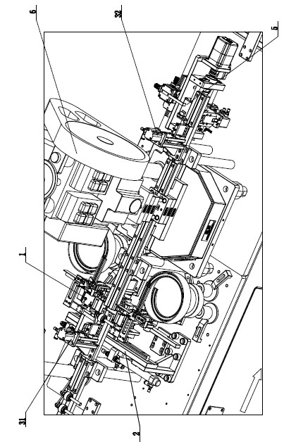
[0031] Such as figure 1 , 2 As shown, the contact riveting machine includes a first strip positioning and pressing device 31, a contact feeding device 2, a contact riveting device 6, a second strip positioning and pressing device 32, a strip Feeding device 5, roll material receiving device (figure omitted), above-mentioned devices are all connected with main control circuit 10, and are controlled by it, and main control circuit 10 is located at an end of body 9. In addition, it also includes a cam jacking device 4 arranged under the contact clamping device 1 of the contact feeding device 2 . Here, the structure of the first strip positioning and pressing device 31 is exactly the same as that of the second strip positioning and pressing device 32 .

[0032] Among them, the material belt conveying track ...


PUM


Abstract

The invention belongs to the technical field of riveters and particularly discloses a contact riveter, which comprises a machine body, a first material band positioning and pressing device, a contact feeding device, a contact riveting device, a second material band positioning and pressing device, a material band feeding device, a cam ejecting device, a material band feeding track, wherein the first material band positioning and pressing device, the contact feeding device, the contact riveting device, the second material band positioning and pressing device and the material band feeding device are arranged on the machine body in turn; the cam ejecting device is arranged below the contact feeding device; all devices are connected with and controlled by a main control circuit arranged on one end of the machine body; and the material band feeding track carries a material band, runs through the middle of the first material band positioning and pressing device and the contact feeding device and extends to the contact riveting device, the second material band positioning and pressing device and the material band feeding device. In the invention, the low speed and low efficiency problemsof a riveting process combining a working mechanism and manual operation, the contact riveter adopting a fully automatic flow has the advantages of high assembly quality and high efficiency, and operation environment is improved.

Description

technical field [0001] The invention relates to the technical field of riveting machines, in particular to a contact riveting machine. Background technique [0002] In electrical components, the contact is a common structural part. Its structural feature is that the contact is assembled in the prefabricated hole of the coil, and then the contact is fixed on the coil by riveting. The characteristic of this type of product is that it is used The range is extremely wide, the number of parts is extremely large, and the size of the contact is small. For a long time, the assembly operation between the contact and the coil has been completed by the working mechanism combined with a large amount of manual labor. [0003] The commonly used assembly method is to use the existing press and supplemented with mold feeding, and the loading and unloading are all completed by manual operation. Among them, the positioning and alignment of the contact point and the prefabricated hole on the ...

Claims


Application Information

Patent Timeline
IPC IPC(8): B21D39/00B21D43/00
Inventor 周俊雄周俊豪周俊杰
Owner 周俊雄
Why Eureka
Try Eureka