
LED illuminating lamp

A technology of LED lighting and LED chips, which is applied in the direction of lighting devices, lighting and heating equipment, parts of lighting devices, etc., can solve the problems of limited lighting angle, low lighting angle, and affecting lighting effects, etc., so as to improve the service life , Expand the lighting area and reduce energy consumption

Inactive Publication Date: 2011-07-13
DEQING NEW MINGHUI ELECTRIC LIGHTING
View PDF3 Cites 5 Cited by
  • Summary
  • Abstract
  • Description
  • Claims
  • Application Information

AI Technical Summary

Problems solved by technology

[0004] However, LED has the disadvantage of low illumination angle. Its light is directional, and the light angle is limited, which will cause lighting blind spots in some areas around the LED and affect its lighting effect.

Method used


Image

  • LED illuminating lamp
  • LED illuminating lamp
  • LED illuminating lamp

Examples


Embodiment

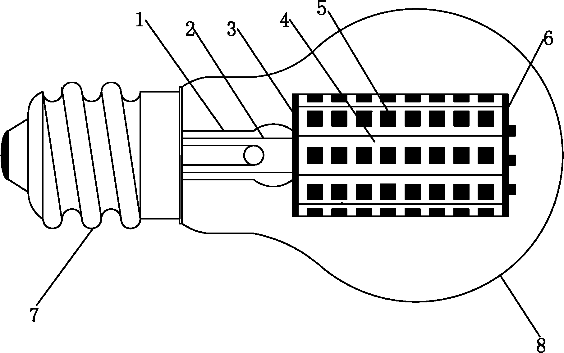
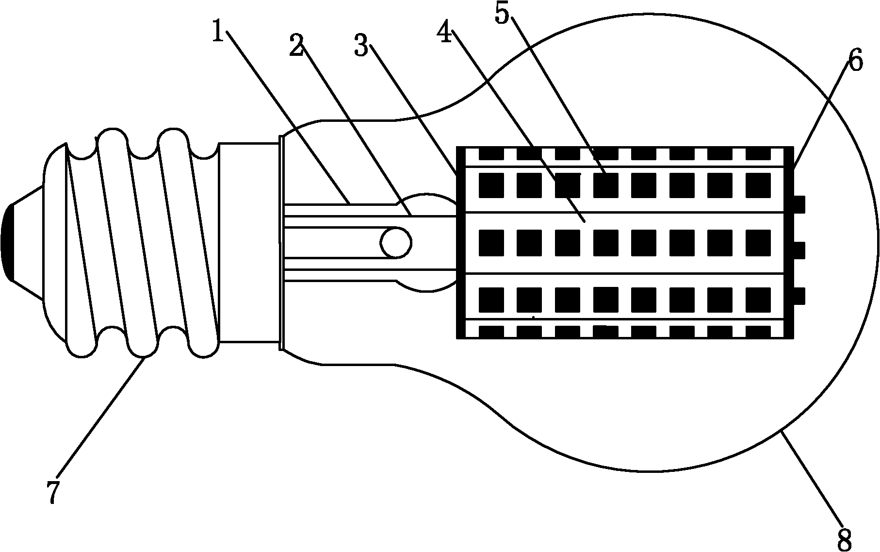
[0017] Embodiment: an LED lighting lamp, including a lamp cap 7, a glass bulb 8, a glass stem 1 is provided in the glass bulb 8, a wire 2 is drawn out of the glass stem 1, and a first copper-clad laminate is fixed on the top of the glass stem 1 3. There are eight circuit boards 4 that are closely adjacent to each other and form a circle at the periphery of the first copper-clad laminate 3. The circuit boards 4 are all perpendicular to the first copper-clad laminate 3, and soldered on each circuit board 4. There are 8 LED chips 5, and the 8 LED chips 5 are arranged in a line on the circuit board 4. A second copper-clad board 6 is fixed on the top of the circuit board 4, and there are also multiple soldered boards on the second copper-clad board 6. A LED chip 5 is provided with an LED driver (not shown in the figure) in the cavity surrounded by the first copper clad board 3, the circuit board 4 and the second copper clad board 6, and the wire 2 is connected to the LED driver. The...


PUM


Abstract

The invention discloses a light emitting diode (LED) illuminating lamp. The lamp comprises a lamp cap and a glass shell, wherein a glass core column is arranged in the glass shell; a wire is led out of the glass core column; the top of the glass core column is fixedly provided with a first copper-clad plate; a plurality of circuit boards which are tightly adjacent and enclose a circle are arranged at the periphery of the first copper-clad plate and are vertical to the first copper-clad plate; a plurality of LED chips are welded on each circuit board; a second copper-clad plate is fixed on the tops of the circuit boards; a plurality of LED chips are welded on the second copper-clad plate; an LED driver is arranged in a cavity formed by enclosing the first copper-clad plate, the circuit boards and the second copper-clad plate; the wire is connected with the LED driver; and the circuit boards and the second copper-clad plate are connected with the LED driver. In the LED illuminating lamp, the plurality of circuit boards with the LED chips enclose the circle, and the LED chips are arranged on one copper-clad plate on the tops of the circuit boards, so that an illuminating area is expanded, dead zone free illumination is realized, service life can be prolonged, and energy consumption is reduced.

Description

technical field [0001] The invention relates to the technical field of LEDs, in particular to an LED lighting lamp. Background technique [0002] Energy saving and emission reduction is a hot spot in the world today. Due to the rapid development of LEDs, it is an inevitable trend to replace incandescent lamps with LEDs. [0003] LED is a solid-state light emitting device, which has the advantages of energy saving and high efficiency, and adapts to the sustainable development goals of energy saving and emission reduction proposed in today's world. Home lighting requires a popular LED light bulb that is energy efficient. [0004] However, LED has the disadvantage of low illumination angle, its light emission is directional, and its light angle is limited, which will cause lighting blind spots in some areas around the LED and affect its lighting effect. Contents of the invention [0005] The present invention overcomes the disadvantages of the above-mentioned prior art, and...

Claims


Application Information

Patent Timeline
Patent Type & Authority Applications(China)
IPC IPC(8): F21S2/00F21V19/00F21V23/00F21Y101/02F21K9/23F21Y115/10
Inventor 马人秀钱勇顾碧忠
Owner DEQING NEW MINGHUI ELECTRIC LIGHTING
Learn More