
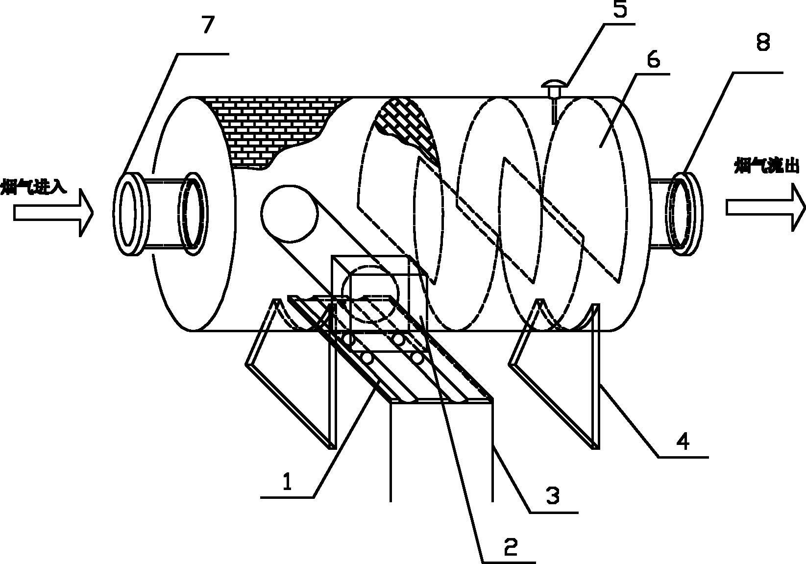
Cremation flue gas purification combustion device

A combustion device and flue gas purification technology, applied in the field of cremation flue gas purification combustion devices, can solve the problems of unsatisfactory purification effect and insufficient flue gas combustion, and achieve the effect of reducing workload and prolonging residence time.

Inactive Publication Date: 2011-07-13
民政部一零一研究所
View PDF6 Cites 3 Cited by
  • Summary
  • Abstract
  • Description
  • Claims
  • Application Information

AI Technical Summary

Problems solved by technology

Its shortcoming is that the flue gas produced by the cremation machine is not fully burned, and the purification effect is not ideal

Method used


Image

  • Cremation flue gas purification combustion device
  • Cremation flue gas purification combustion device

Examples


Embodiment Construction

[0019] Below with reference to accompanying drawing and preferred embodiment, technical scheme of the present invention is described in detail:

[0020] Such as figure 1 As shown, the structure of the cremation flue gas purification combustion device as a whole includes a burner slide rail 1, a burner 2, a burner bracket 3, a burner controller and a combustion chamber. The combustion chamber is provided with a temperature sensor 5, a baffle 6, an air inlet 7 and an air outlet 8, and the baffle 6 is arranged inside the combustion chamber. The burner slide rail 1 is arranged on the top of the burner bracket 3, the burner 2 is arranged on the burner slide rail 1 top, and the bottom of the whole combustion chamber is provided with two combustion chamber supports 4, and the combustion chamber support 4 is used to support the combustion chamber. The combustion chamber is provided with an opening, and the burner 2 enters the interior of the combustion chamber through the burner slid...


PUM


Abstract

The invention discloses a cremation flue gas purification combustion device, which comprises combustor sliding rails, a combustor, a combustor bracket, a combustor controller and a combustion chamber, wherein the combustion chamber is provided with an opening, a temperature sensor, spoilers, a gas inlet and a gas outlet; the spoilers are arranged in the combustion chamber; the combustor sliding rails are arranged on the upper part of the combustor bracket; and the combustor is arranged on the upper parts of the combustor sliding rails. The cremation flue gas purification combustion device reduces the workload of cremation operators, and can be started to seal incompletely combusted substances in cremation flue gases in the device before the cremation operators starts a combustion program and remove the incompletely combusted substances in advance before the cremation flue gases are emitted out of a chimney.

Description

technical field [0001] The invention relates to the field of cremation equipment in the funeral industry, in particular to a cremation flue gas purification combustion device. Background technique [0002] According to the "Statistical Report on the Development of Civil Affairs in 2009", by the end of 2009, 1,729 funeral homes across the country had installed 5,123 cremation machines, with an annual cremation volume of 4.542 million. The cremation machines currently in use mainly include fuel oil cremation machines (accounting for more than 85% of the total), gas-fired cremation machines (accounting for about 10% of the total) cremation machines, and other cremation machines such as plasma torches (at this stage) Just entered the experimental stage), coal-fired cremation machines (old furnaces that have not been completely eliminated) and so on. As the mainstream products, fuel oil and gas cremation machines, in the initial stage of cremation, will encounter working conditi...

Claims


Application Information

Patent Timeline
Patent Type & Authority Applications(China)
IPC IPC(8): F23G7/06
Inventor 王玮吴桐李大涛肖成龙鲁琦陈曦邢啸林尹荔堃李伯森
Owner 民政部一零一研究所
Learn More