Limiting assembling structure for heat pipe and heat conduction seat

A limit and heat pipe technology, applied in heat exchange equipment, heat exchanger shells, indirect heat exchangers, etc., can solve problems such as falling off, increasing material and manufacturing costs, and inability to concentrate heat pipes.

Inactive Publication Date: 2011-07-13
DONG GUAN HAN XU HARDWARE & PLASTIC TECH CO LTD
View PDF6 Cites 7 Cited by
  • Summary
  • Abstract
  • Description
  • Claims
  • Application Information

AI Technical Summary

Problems solved by technology

[0003] However, as mentioned above, if no adhesive such as solder is used as a fixation between the heat pipe and the heat conduction seat, the contact surface between the heat pipe and the heat conduction seat is still in an arc shape, which is prone to slipping, even falling off, and other misalignment problems, and When there are multiple heat pipes to be combined, the distance between the heat pipes is increased because the grooves are slightly elliptical, making it impossible to effectively concentrate the heat pipes in the application of multiple heat pipes; and if adhesives such as solder are used as When fixing, there are troubles such as too little solder can not stick, too much is easy to overflow and affect the appearance, and the use of solder also increases the cost of materials and manufacturing, which is not ideal

Method used


Image

  • Limiting assembling structure for heat pipe and heat conduction seat
  • Limiting assembling structure for heat pipe and heat conduction seat
  • Limiting assembling structure for heat pipe and heat conduction seat

Examples


Embodiment Construction

[0033] The present invention will be further described below in conjunction with the accompanying drawings and specific embodiments.

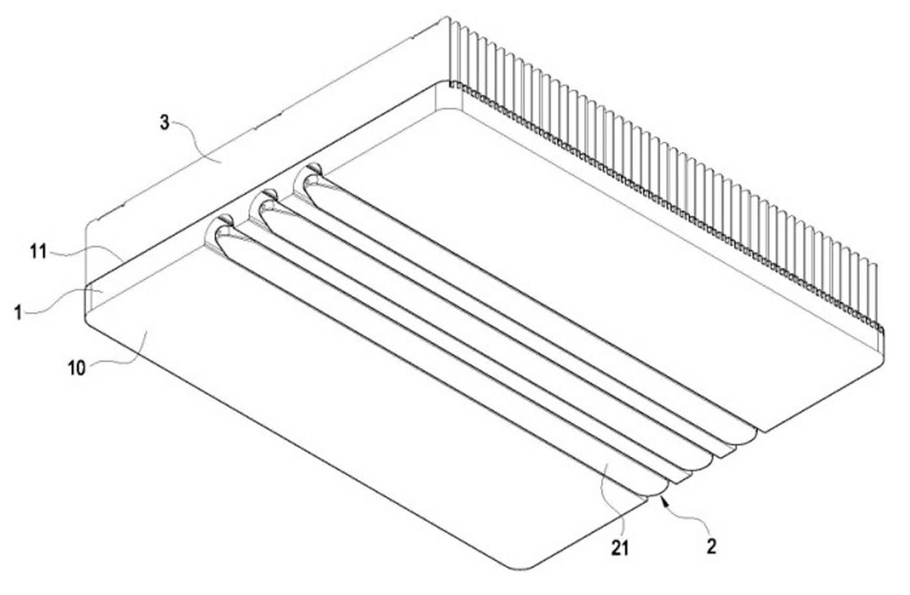
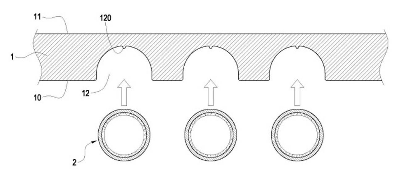
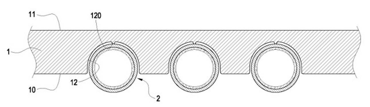
[0034] see figure 1 , is a three-dimensional combination diagram of the present invention. The present invention provides a limited assembly structure of a heat pipe and a heat conduction seat, which includes a heat conduction seat 1 and at least one heat pipe (Heat pipe) 2 pressed against the heat conduction seat 1 so that it can be combined with the heat conduction seat through the heat pipe 2 1, to increase the heat transfer effect of the heat conduction seat 1; where:

[0035] The heat conduction seat 1 can be made of copper or aluminum and other materials with good thermal conductivity, which can be used as a base for attaching a heat source such as a heat sink, and has at least one bottom surface 10 for attaching a heat source, and A top surface 11 opposite to the other side of the bottom surface 10; and in the embodiment of the present...


PUM


Abstract

The invention relates to a limiting assembling structure for a heat pipe and a heat conduction seat, which comprises the heat conduction seat and at least one heat pipe pressed against the heat conduction seat, wherein the heat conduction seat is provided with a surface; a groove is formed on the surface in a sunken way; a limiting rib is integrally protruded on the surface in the groove; the heat pipe is pressed against the interior of the groove of the heat conduction seat; and the limiting rib is nipped into the surface of the part, positioned in the groove, of the heat pipe to form a sunken limiting nick in fit with the limiting rib on the surface of the part, positioned in the groove, of the heat pipe. The limiting rib is nipped into the heat pipe to form the limiting nick, so the heat pipe is difficult to deviate in the groove.

Description

technical field [0001] The present invention is related to a heat dissipation structure, especially a limited assembly structure of a heat pipe and a heat conduction seat. Background technique [0002] Press, the use of heat pipes (Heat pipe) combined with the heat conduction seat to increase the heat transfer efficiency of the heat conduction seat is one of the common technical means or structures on radiators today. In the past, when it was desired to combine the heat pipe on the heat transfer seat, the heat pipe was usually fixed in the groove of the heat transfer seat through solder, or the surface in contact with the heat pipe was deformed by using a slightly elliptical arc groove, thereby preventing When the heat pipe is combined in the groove of the heat conduction seat, the problem of sliding and other falling off occurs. [0003] However, as mentioned above, if no adhesive such as solder is used as a fixation between the heat pipe and the heat conduction seat, the ...

Claims


Application Information

Patent Timeline
Patent Type & Authority Applications(China)
IPC IPC(8): F28D15/02F28F9/26
CPCF28D15/0233F28F2275/12F28D15/0275H01L23/427H05K7/20F28D15/02
Inventor 黄崇贤
Owner DONG GUAN HAN XU HARDWARE & PLASTIC TECH CO LTD
Why Eureka
Try Eureka