Plate-type pulsating heat pipe with double-side grooves

A pulsating heat pipe and double-sided groove technology, which is applied in heat exchange equipment, indirect heat exchangers, lighting and heating equipment, etc., can solve the problems such as the lack of a unified explanation for the pulsating heat transfer mechanism and the insufficient attention to the application of pulsating heat pipes. Achieve the effect of improving the internal working medium distribution and heat transfer uniformity, good heat transfer capacity, and convenient vacuuming and filling.

Inactive Publication Date: 2012-05-30
CHANGSHA UNIVERSITY OF SCIENCE AND TECHNOLOGY
View PDF4 Cites 1 Cited by
  • Summary
  • Abstract
  • Description
  • Claims
  • Application Information

AI Technical Summary

Problems solved by technology

Although the high-efficiency heat transfer characteristics of pulsating heat pipes have been generally recognized, due to the fact that the research on the mechanism of pulsating heat transfer has not yet formed a unified explanation, the scientific and technological circles still pay a lot of attention to theoretical discussions, but the application of pulsating heat pipes has not attracted enough attention.

Method used


Image

  • Plate-type pulsating heat pipe with double-side grooves
  • Plate-type pulsating heat pipe with double-side grooves
  • Plate-type pulsating heat pipe with double-side grooves

Examples


Embodiment 1

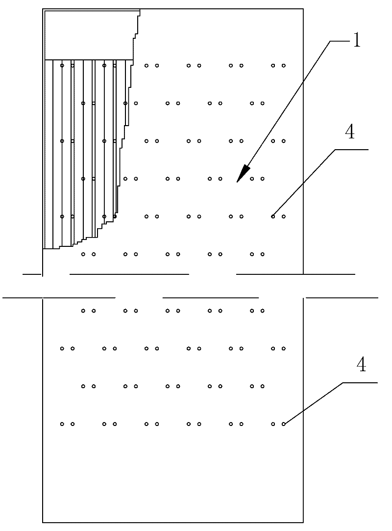
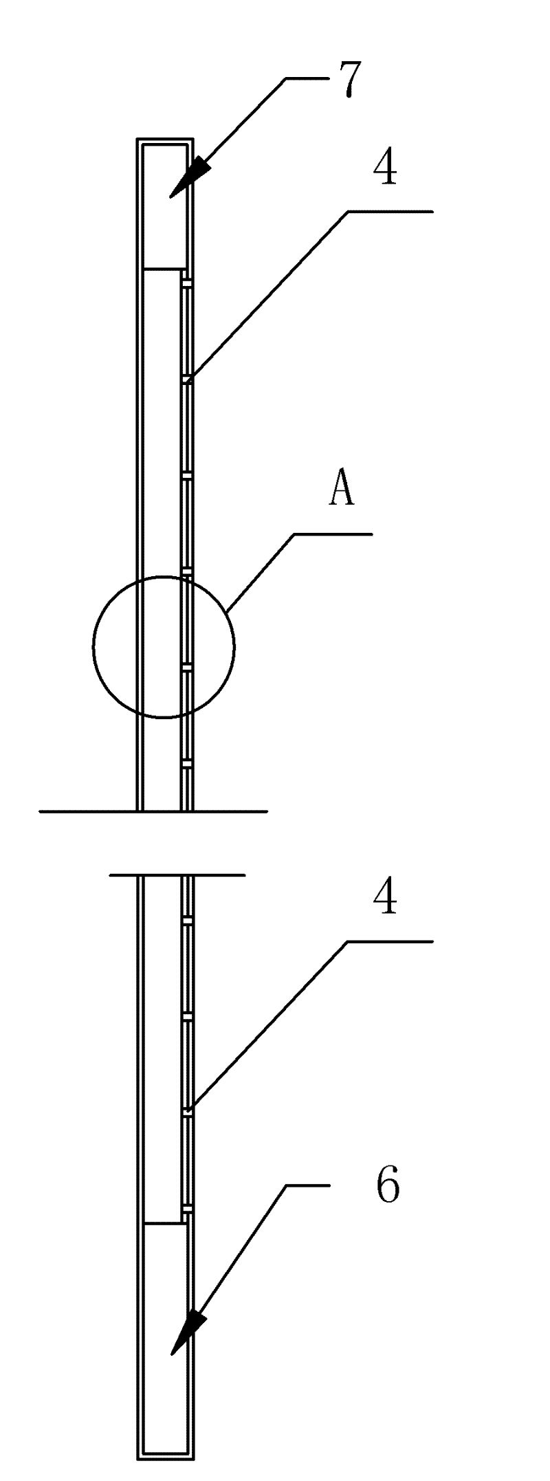
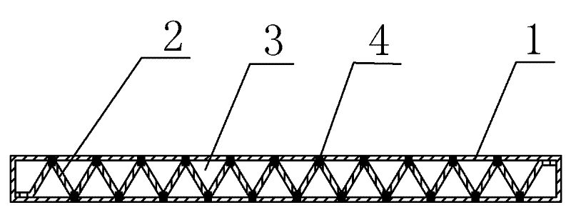
[0048] See attached figure 1 , 2 , 3, 4, the double-sided channel plate-type pulsating heat pipe of the present invention includes a shell 1, a folded plate 2. The cross section of the shell 1 is a rectangular closed box; the folded plate 2 is composed of a periodic triangular shape The folded plate 2 is inserted into the housing 1, so that a plurality of pulsating channels 3 are formed between the folded plate 2 and the inner surface of the housing 1; The ribs are connected to the inner surface of the shell 1 by discontinuous spot welding joints 4, so that a micro seam 5 is formed between adjacent channels; the shell 1 is closed, evacuated, and filled with distilled water as a working substance; The folded plate 2 is not flush with the ends 6 and 7 of the shell 1; the equivalent diameter of the pulsating channel 3 is 0.5-1mm; the shell and the folded plate are made of stainless steel; The length is 5-50mm, and the width of the micro slit 5 is 3-30μm.

[0049] The maximum equiva...

Embodiment 2

[0051] See attached Figure 5 , 6 , The double-sided channel plate type pulsating heat pipe of the present invention includes a shell 1, a folded plate 2, the cross section of the shell 1 is a rectangular closed box; the folded plate 2 is a curved panel composed of a periodic sine wave shape , The shell 1 and the folded plate 2 are integrally stretched or integrally extruded, the folded plate 2 is in the shell 1, and the inner surface of the folded plate 2 and the shell 1 A number of pulsating channels 3 are formed between; the shell 1 is closed, evacuated and filled with working medium R123; the folded plate 2 is not flush with the end of the shell 1; the equivalent diameter of the channel is 0.5~3.5mm; The shell and the folded plate are made of aluminum alloy.


PUM


Abstract

The invention relates to a plate-type pulsating heat pipe with double-side grooves, comprising a casing and a bent plate. The cross section of casing is a rectangular closed box; the bent plate is a curved plate formed by a periodical winding shape, and the cross section of the bent plate is shaped like continuous triangles, or sinuidal or others periodic winding; the bent plate is inserted in the casing, and a plurality of pulsating grooves are formed between the bent plate and the inner surface of the casing, bent edges of the bent plate and the inner surface of the casing are connected through discontinuous spot welding, and slit communication is formed between the adjacent grooves; and the casing is closed, vacuumized and filled with working mediums. The plate-type pulsating heat pipewith the double-side grooves integrates the pulsating, flat plate, capillary and strengthening heat transfer and has excellent heat dissipation and cooling performances; the equivalent thermal conductive coefficient of the plate-type pulsating heat pipe with the double-side grooves is higher than that of an aluminum extruded heat radiator by more than two orders of magnitude and 2-3 times that ofa related flat heat pipe; an excellent heat dissipation function is also provided by horizontal installation due to capillary grooves, and the application is facilitated. Therefore, the plate-type pulsating heat pipe with the double-side grooves is particularly suitable for heat dissipation and cooling of various chips and electronic components.

Description

Technical field [0001] The invention discloses a double-sided channel plate type pulsating heat pipe. It belongs to the technical field of heat exchange equipment. Background technique [0002] Electronic components such as chips in the electronic and microelectronics field, thyristors in the electromechanical field, silicon controlled rectifiers, semiconductor light-emitting diodes (LED), and large-scale integrated circuits (LSLchip) are widely used in production and life. These chips and components generate a lot of heat when they work, and they must be dissipated in time to ensure the safe and stable operation of the equipment. Studies have shown that the operating temperature of electronic components is generally -5~+70℃. If the temperature of a single semiconductor component increases by 10℃, the system reliability will drop by 50%. More than 55% of the electronic equipment failures are due to excessive temperature. caused. It can be seen that the heat dissipation of chip...

Claims


Application Information

Patent Timeline
Patent Type & Authority Patents(China)
IPC IPC(8): F28D15/02F28F21/08H01L23/427
CPCF28D15/0266
Inventor 夏侯国伟
Owner CHANGSHA UNIVERSITY OF SCIENCE AND TECHNOLOGY
Why Eureka
Try Eureka