Compact CO2 removal system driven by thermal power through mixed working medium

A mixed working fluid, thermally driven technology, applied in the fields of carbon compounds, air quality improvement, lighting and heating equipment, etc., can solve the problems of large consumption of regenerative thermal energy and complex equipment structure, achieve compact system, simplify equipment structure, promote The effect of the spray effect

Active Publication Date: 2016-01-20
TIANJIN UNIV
View PDF9 Cites 0 Cited by
  • Summary
  • Abstract
  • Description
  • Claims
  • Application Information

AI Technical Summary

Problems solved by technology

[0007] The purpose of the present invention is to overcome the shortcomings of the existing decarbonization equipment, such as large regeneration heat energy consumption and complex equipment structure, and provide a low-energy decarbonization system equipment suitable for small and medium-sized carbon-containing flue gas sources and compact in structure. The low-temperature condensed mixed working fluid produced by the condensing liquid collector is mixed with the high-temperature mixed working medium produced by the desorption generator to produce the medium-temperature mixed working medium required by the absorber 2, which saves the condensation process before the mixed working medium enters the absorber and reduces Reduce energy consumption, improve the purity of carbon dioxide and make the system more compact

Method used


Image

  • Compact CO2 removal system driven by thermal power through mixed working medium

Examples


Embodiment Construction

[0019] The technical solution of the present invention will be further described in detail below in conjunction with the accompanying drawings and specific embodiments, and the described specific embodiments are only for explaining the present invention, and are not intended to limit the present invention.

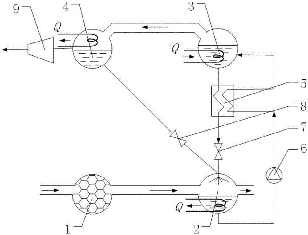
[0020] The invention utilizes the heat exchange between the mixed solution after absorbing carbon dioxide and the mixed working medium after desorbing carbon dioxide to improve the heat utilization efficiency of the desorption heat source, and forms the mixed working medium required for absorbing carbon dioxide by mixing the low-temperature mixed working medium and the high-temperature mixed working medium. The temperature of the substance can reduce the loss of heat when the absorption mixed working fluid is further condensed, and at the same time increase the concentration of carbon dioxide in the condenser. Realize flue gas CO in the industrial field 2 At the same time ...


PUM


Abstract

The invention discloses a compact CO2 removal system driven by thermal power through a mixed working medium. The compact CO2 removal system comprises an absorber, a solution pump, a solution heat exchanger, a desorption generator, a condensation liquid collector and a CO2 compressor which are sequentially connected with a smoke preprocessing unit. Mixed gas containing carbon dioxide enters the absorber to be absorbed by the mixed working medium so that a mixed solution containing carbon dioxide can be formed and can enter the desorption generator to be separated. The compact CO2 removal system overcomes the defects that an existing decarbonization device is high in regenerated heat energy consumption, complex in device structure and the like. The low-energy-consumption decarbonization device which is suitable for small and medium-sized carbon-containing smoke sources and is compact in structure is provided. Meanwhile, the low-temperature condensation mixed working medium generated by the condensation liquid collector is mixed with the high-temperature mixed working medium generated by the desorption generator so as to generate the medium-temperature mixed working medium required by the absorber, and the structure of the system can be more compact while the energy consumption is lowered. The control over the low-energy-consumption running can be conducted through a connection manner of system devices according to absorption type circulation.

Description

technical field [0001] The invention relates to a method for removing CO by using mixed working fluid 2 technology, specifically involving a compact CO removal system driven by heat using a mixed working fluid 2 system device. Background technique [0002] The development of industrial technology has led to a sharp increase in the consumption of fossil fuels, resulting in an increase in the concentration of carbon dioxide in the atmosphere and global warming. 2 Releasing into the air after removal has become an important strategic option to deal with climate change. Therefore, the key to tackling global climate change and acid rain pollution is to control carbon dioxide emissions. The recovered and separated carbon dioxide has a wide range of industrial application values. It can not only be used as a source of carbon elements, but also can generate a variety of carbon products related to the national economy and people's livelihood through different reaction pathways, wh...

Claims


Application Information

Patent Timeline
Patent Type & Authority Applications(China)
IPC IPC(8): F25B15/16B01D53/78C01B31/20F23J15/02C01B32/50
CPCY02A50/20Y02E20/32Y02P20/151
Inventor 邓帅刘良旭赵军安青松高留花
Owner TIANJIN UNIV
Why Eureka
Try Eureka