
Road border detection method based on infrared image
A boundary detection and infrared image technology, applied in the field of image analysis and computer vision, can solve problems such as difficult application, and achieve the effect of real-time processing, reduced resolution, and low time complexity
- Summary
- Abstract
- Description
- Claims
- Application Information
AI Technical Summary
Problems solved by technology
Method used
Image

Examples
Embodiment Construction
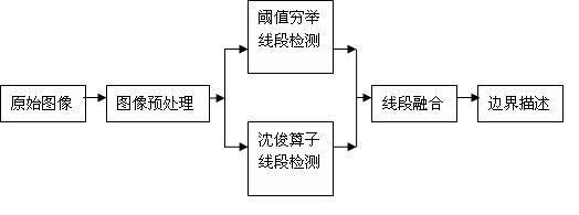
[0019] The present invention is based on the road boundary detection method of infrared image, and its steps are:
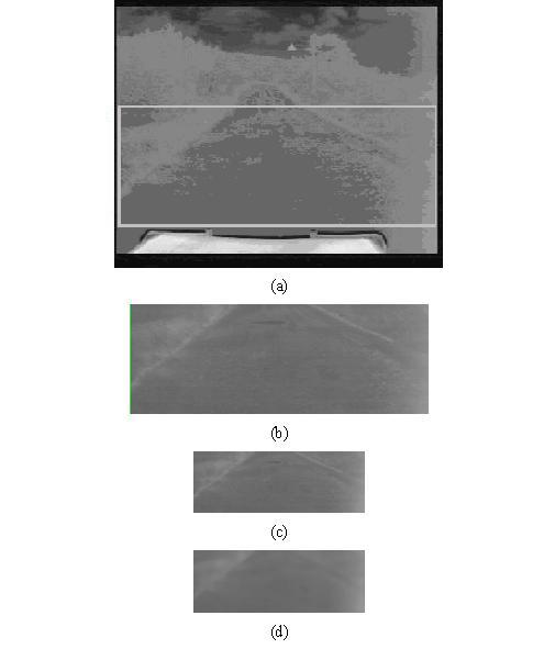
[0020] The first step: image preprocessing, designate the region of interest in the image, and perform median filter processing after reducing the resolution to improve the consistency of the road area, and reduce the processing area without reducing the detection accuracy, saving processing time.
[0021] Manually specify a rectangular area on the image, so that the rectangular area contains the left and right road boundaries as much as possible, and at the same time excludes the non-road boundaries as much as possible. The image row coordinate Y1 on the upper side of the rectangular area is set according to the farthest distance requirement for road boundary line detection. The image row coordinate Y2 below is set as the row coordinate of the front end on the image, the image column coordinates on the left and right sides are respectively set to X and Width-X (W...
PUM
 Abstract
Description
Claims
Application Information