A discontinuous reception method and system
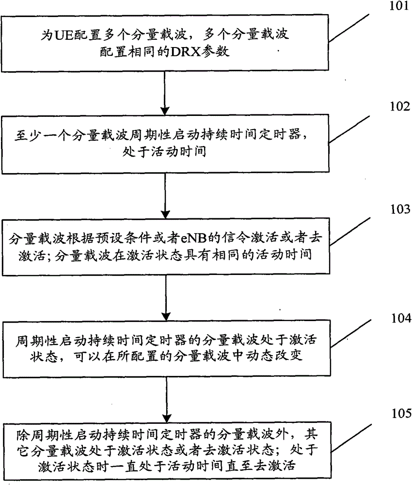
A receiving method and technology of duration, applied in the field of communication, can solve the problems of not receiving system information, not monitoring, or not performing channel quality indication, etc., to achieve the effects of increasing cell capacity, reducing power consumption, and saving signaling overhead
- Summary
- Abstract
- Description
- Claims
- Application Information
AI Technical Summary
Problems solved by technology
Method used
Image
Examples
example 1
[0129] Such as Figure 5 As shown, a DRX method is described as follows:
[0130] Assuming that the UE is configured with three component carriers CC1, CC2, and CC3, it mainly describes the situation that each configured component carrier periodically starts a duration timer in an activated state.
[0131] Scenario 1: The component carriers CC1, CC2, and CC3 periodically start the DRX duration timer according to the configured DRX cycle and DRX start offset value, and are in active time.
[0132] Scenario 2: The component carrier CC1 receives the PDCCH indicating the downlink allocation or uplink grant of the component carrier, starts the DRX inactivity timer, and enters the DRX inactivity time when the DRX inactivity timer expires; although the component carriers CC2 and CC3 have no data reception Or the sending behavior is consistent with the active time of the component carrier CC1; that is, during the running period of the duration timer or the DRX inactivity timer, the c...
example 2
[0137] Such as Figure 6 As shown, a DRX method is described as follows:
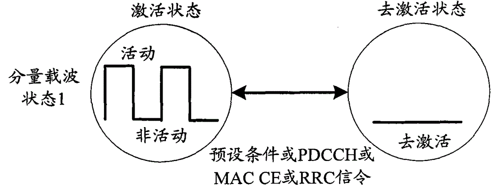
[0138] Assuming that the UE is configured with three component carriers CC1, CC2, and CC3, it is mainly described that the component carriers are deactivated according to preset conditions and the component carriers that periodically start the duration timer change dynamically.
[0139] Scenario 1: The component carrier CC1 is a component carrier that starts the duration timer periodically, starts the duration timer according to the configured short DRX cycle or long DRX cycle and the DRX start offset value, and is in active time; the component carriers CC2, CC3 is in a deactivated state.
[0140] Scenario 2: The component carrier CC1 receives the downlink allocation or uplink grant indicated by the PDCCH within a duration, and starts the DRX inactivity timer; the component carriers CC2 and CC3 continue to be in the deactivated state.
[0141] Scenario 3: eNB activates component carrier CC2 through PD...
example 3
[0152] Such as Figure 7 As shown, a DRX method is described as follows:
[0153] Assuming that the UE is configured with 3 component carriers CC1, CC2, and CC3, it mainly explains the dynamic change of the component carrier according to the deactivation of the eNB signaling and the component carrier that periodically starts the duration timer. After activation, it is the periodic startup duration timer A component carrier can be active or inactive when activated.
[0154] Scenario 1: The component carrier CC1 starts the duration timer according to the configured short DRX cycle or long DRX cycle and the DRX start offset value, and is in the active time; the component carriers CC2 and CC3 are in the deactivated state.
[0155] Scenario 2: The eNB activates the component carrier CC2 by using the PDCCH signaling through the component carrier CC1.
[0156] Scenario 3: The component carrier CC1 receives the PDCCH indicating downlink allocation or uplink grant, and starts the DRX...
PUM
 Abstract
Description
Claims
Application Information
 - R&D
- Intellectual Property
- Life Sciences
- Materials
- Tech Scout
- Unparalleled Data Quality
- Higher Quality Content
- 60% Fewer Hallucinations
Browse by: Latest US Patents, China's latest patents, Technical Efficacy Thesaurus, Application Domain, Technology Topic, Popular Technical Reports.
© 2025 PatSnap. All rights reserved.Legal|Privacy policy|Modern Slavery Act Transparency Statement|Sitemap|About US| Contact US: help@patsnap.com


