Vertical crusher
A pulverizer and vertical technology, applied in the field of vertical pulverizers, can solve the problems of slow discharge speed and low processing efficiency, and achieve the effect of fast discharge speed and fast pulverization speed.
- Summary
- Abstract
- Description
- Claims
- Application Information
AI Technical Summary
Problems solved by technology
Method used
Image

Examples
Embodiment Construction
[0014] The present invention will be further described below in conjunction with drawings and embodiments.
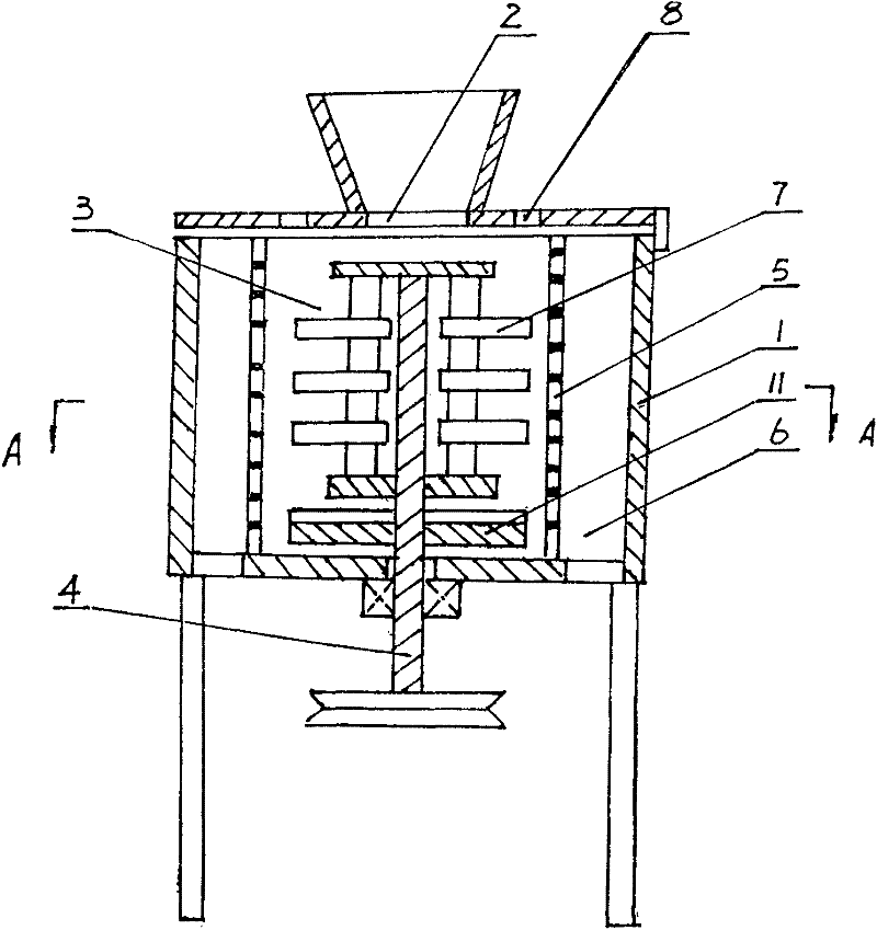
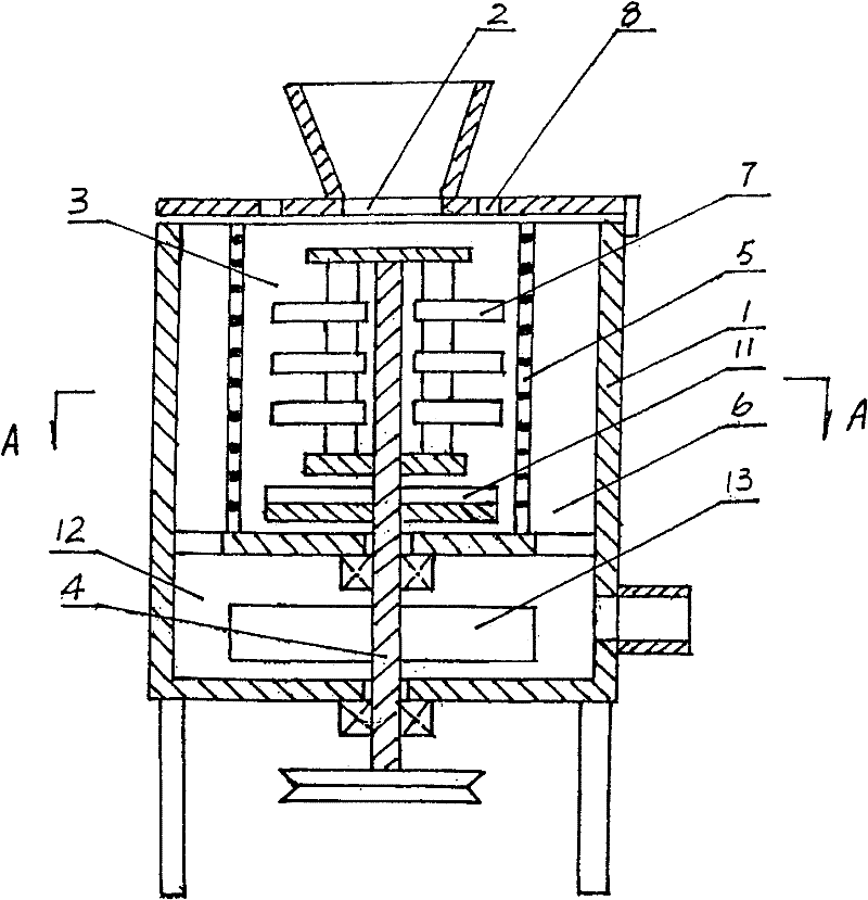
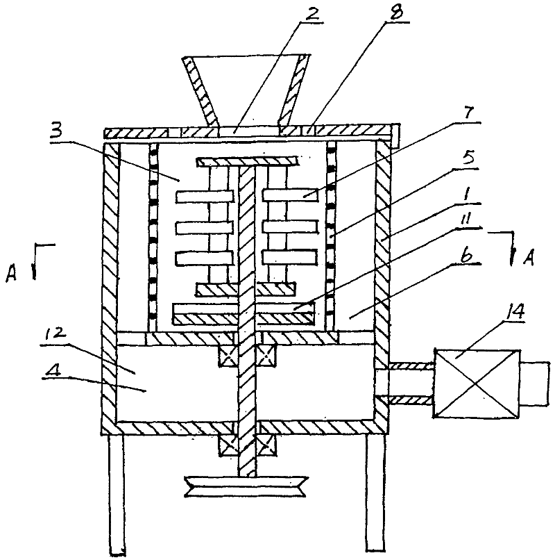
[0015] exist figure 1 , Figure 4 , Figure 5 In the first embodiment shown, the top of the pulverizer housing 1 is formed with a feed inlet 2, and a pulverizer chamber 3 is formed in the pulverizer housing 1, and the pulverizer shaft 4 is longitudinally installed in the pulverizer housing 1, and the The mesh screen 5 is installed in the crushing chamber 3, the discharge channel 6 is formed between the annular mesh screen 5 and the crushing machine shell 1, the hammer blade 7 is mounted on the crushing machine shaft 4 in the crushing chamber 3, and the The top is shaped on air vent 8. It is also possible to cancel the hammer blade 7 and install the crushing plate 9 with the hammer rod 10 on the crushing machine shaft 4 in the crushing chamber 3 . It is also possible to install the hammer blade 7 and the crushing plate 9 on which the hammer rod 10 is fixed on the cru...
PUM
 Abstract
Description
Claims
Application Information
 - R&D
- Intellectual Property
- Life Sciences
- Materials
- Tech Scout
- Unparalleled Data Quality
- Higher Quality Content
- 60% Fewer Hallucinations
Browse by: Latest US Patents, China's latest patents, Technical Efficacy Thesaurus, Application Domain, Technology Topic, Popular Technical Reports.
© 2025 PatSnap. All rights reserved.Legal|Privacy policy|Modern Slavery Act Transparency Statement|Sitemap|About US| Contact US: help@patsnap.com