Hydraulic shaft detaching device

An off-axis, hydraulic technology, applied in the direction of metal processing, metal processing equipment, manufacturing tools, etc., can solve the problems of difficult disassembly, long operation cycle, and easily damaged equipment, so as to shorten the disassembly time, reduce labor intensity and economic benefits obvious effect

Inactive Publication Date: 2012-07-11
XINAN COAL IND ZAOZHUANG COAL MINING GROUP
View PDF0 Cites 0 Cited by
  • Summary
  • Abstract
  • Description
  • Claims
  • Application Information

AI Technical Summary

Problems solved by technology

[0002] In the long-term production practice, due to the long operating period of the equipment, the pins and shafts of the mechanical structure of the equipment are often damaged. At present, it is necessary to use a manual lever hammer to disassemble. The method is difficult to disassemble and assemble when replacing on-site underground. It takes a long time, and at the same time, it is easy to damage the equipment, so as to affect the production

Method used


Image

  • Hydraulic shaft detaching device
  • Hydraulic shaft detaching device
  • Hydraulic shaft detaching device

Examples


Embodiment Construction

[0009] The present invention will be further described below in conjunction with accompanying drawing and specific embodiment:

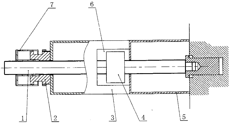
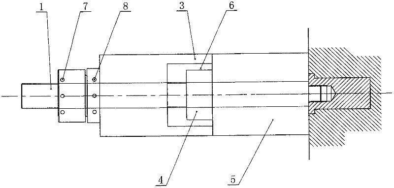
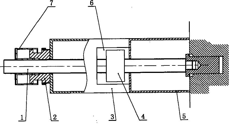
[0010] The invention as figure 1 , 2 As shown, a hydraulic shaft extractor includes a screw 1, which is characterized in that: the right part of the screw 1 is covered with a first-level sleeve 5, and the left side of the first-level sleeve 5 is designed with a lock nut 4, and the lock nut 4 and the screw 1 Threaded connection, the left side of the lock nut 4 is designed with a secondary sleeve 3, the secondary sleeve 3 is sleeved on the screw 1, and the secondary sleeve 3 has a working port 6, the working port 6 corresponds to the lock nut 4, the second The left side of the stage sleeve 3 is designed with a hydraulic nut 2 with an oil injection hole 7 and a dismounting hole 8, and the hydraulic nut 2 is threadedly connected with the screw rod.

[0011] In this embodiment, the lock nut 4 is a hydraulic nut.

[0012] When using the present inventio...


PUM


Abstract

The invention discloses a hydraulic shaft detaching device with a simple structure and convenient to use. The hydraulic shaft detaching device comprises a screw, wherein a first-level sleeve is sleeved on the right part of the screw; a lock nut is arranged on the left side of the first-level sleeve and is in threaded connection with the screw; a second-level sleeve is arranged on the left side ofthe lock nut and sleeved on the screw; a working hole is formed on the second-level sleeve and corresponds to the lock nut; and a hydraulic nut with an oil injection hole and a detaching hole is arranged on the left side of the second-level sleeve, and is in threaded connection with the screw.

Description

technical field [0001] The invention relates to a mining mechanical equipment, in particular to a hydraulic shaft disconnector. Background technique [0002] In the long-term production practice, due to the long operating period of the equipment, the pins and shafts of the mechanical structure of the equipment are often damaged. At present, it is necessary to use a manual lever hammer to disassemble. The method is difficult to disassemble and assemble when replacing on-site underground. It takes a long time, and at the same time, it is easy to damage the equipment, so that it affects production. Contents of the invention [0003] The purpose of the present invention is to provide a hydraulic shaft disconnector with simple structure and convenient use. [0004] In order to achieve the above object, the technical solution adopted by the present invention is: a hydraulic shaft release device, including a screw rod, which is characterized in that: the right part of the screw ...

Claims


Application Information

Patent Timeline
Patent Type & Authority Patents(China)
IPC IPC(8): B23P19/027B23P19/04
Inventor 赵连星赵世俭李涛李文陈君来刘磊谢关友陆德天
Owner XINAN COAL IND ZAOZHUANG COAL MINING GROUP
Why Eureka
Try Eureka