Shock absorption connector for shock detection device in well

A technology of vibration detection and connectors, which is applied in the direction of measurement, wellbore/well components, earthwork drilling and production, etc., can solve the problems of inaccurate signal reception, inaccurate signal analysis, unusability, etc., and achieve accurate signal reception and signal analysis Accurate, avoid mutual rotation effect

Inactive Publication Date: 2011-07-20
中国石化集团胜利石油管理局地球物理勘探开发公司 +1
View PDF6 Cites 0 Cited by
  • Summary
  • Abstract
  • Description
  • Claims
  • Application Information

AI Technical Summary

Problems solved by technology

[0003] The technical problem solved by the present invention is that it is impossible to realize the same-direction connection in the vertical direction and the directional connection in the lateral direction of the multi-stage vibration detection device in the well, and the collected signals cannot be compared and superimposed on the same level, resulting in inaccurate received signals and inaccurate signal analysis. For the technical problem that the vibration detection devices in multi-level wells interfere with each other and cannot be used, a method is provided that can realize the same direction connection in the vertical direction and the directional connection in the lateral direction of the vibration detection devices in multi-level wells. Multiple sets of acquisition signals can be equivalently compared and superimposed. The receiving signal is more accurate, the signal analysis is more accurate, the multi-level well vibration detection device does not interfere with each other, and the well vibration detection device that can work independently is shock-absorbing connector

Method used


Image

  • Shock absorption connector for shock detection device in well
  • Shock absorption connector for shock detection device in well
  • Shock absorption connector for shock detection device in well

Examples


Embodiment Construction

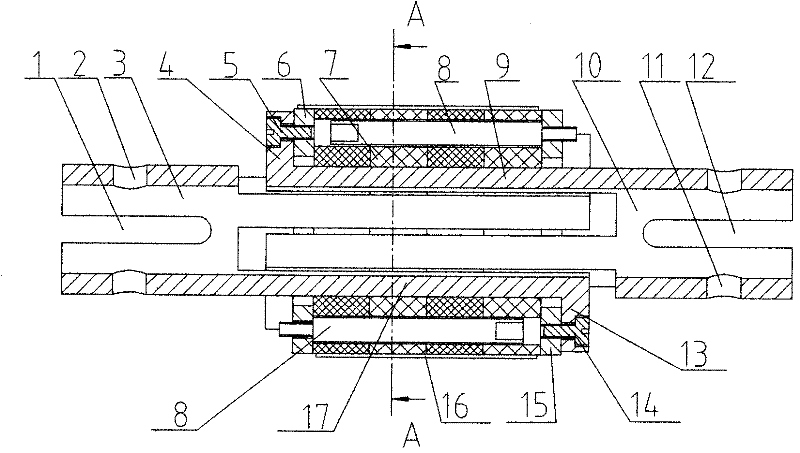
[0012] The shock-absorbing connector of the vibration detection device in the well as shown in the figure is provided with a connecting body, the connecting body is the same left connecting body 3 and right connecting body 10, one end of the left connecting body 3 is evenly distributed with the left connecting claw 17, and the end of the left connecting claw 17 There is a left connecting ear 13, one end of the right connecting body 10 is uniformly distributed with the right connecting claw 9, the end of the right connecting claw 9 is provided with a right connecting ear 4, the left connecting claw 17 and the right connecting claw on the left connecting body 3 and the right connecting body 10 9 are interlaced with each other, and there are two half-ring left flanges 6 and two half-ring right flanges 15 between the left connecting ear 13 and the right connecting ear 4. As can be seen from the figure, the left flange 6 is fastened on the right connecting ear 4 at the end of the ri...


PUM


Abstract

The invention discloses a shock absorption connector for a shock detection device in a well and relates to a shock detection device in a well. Connecting bodies are a left connecting body and a right connecting body with the same structure; a left connecting claw is uniformly distributed at one end of the left connecting body; a left connecting lug is arranged at the tail end of the left connecting claw; a right connecting claw is uniformly distributed at one end of the right connecting body; a right connecting lug is arranged at the tail end of the right connecting claw; the left connecting claw and the right left connecting claw on the left connecting body and the right connecting body are inserted in a staggered mode; two semicircular-ring left flange plates and two semicircular-ring right flange plates are arranged between the left connecting lug and the right connecting lug; fixed rods are arranged between the left flanges and the right flanges; shock absorption pads are arrangedon the fixed rods; a left connecting notch and a left connecting hole are formed at the other end of the left connecting body; and a right connecting notch and a right connecting hole are formed at the other end of the right connecting body. Multi-level shock detection devices in the well do not interfere one another and can independently work, the acquired signals can be equivalently contrasted and superposed, the signals are accurately received, the signals are analyzed accurately, and the connector is applied to connecting the multi-level shock detection devices in the well.

Description

technical field [0001] The invention relates to a vibration detection device in a well, in particular to a shock-absorbing connector for a vibration detection device in a well. Background technique [0002] We know that the existing well vibration detection devices are connected by soft ropes between the well vibration detection devices, which is a flexible connection, and it is impossible to realize the same direction connection in the vertical direction and the directional connection in the lateral direction of the multi-level well vibration detection devices , the collected signals cannot be compared and superimposed on the same level, resulting in inaccurate received signals and inaccurate signal analysis; or a hard connection is used between the vibration detection devices in the well, which causes mutual interference between the multi-level vibration detection devices in the well and cannot work independently, resulting in the final The signal analysis for is inaccurat...

Claims


Application Information

Patent Timeline
Patent Type & Authority Applications(China)
IPC IPC(8): E21B47/00
Inventor 魏福吉颜永安胡立新孙中心刘志田申恒广杨德宽崔汝国吴学兵宋智勇王文争戚全李艳艳
Owner 中国石化集团胜利石油管理局地球物理勘探开发公司
Why Eureka
Try Eureka